Linear half-rate clock and data recovery (CDR) circuit

a clock and data recovery technology, applied in the field of digital interface design, can solve the problems of data dependent jitter or noise, variations in the phase of successive pulses, and full-rate hogge cdr

Active Publication Date: 2006-03-23
MICROCHIP TECH INC
View PDF9 Cites 19 Cited by
  • Summary
  • Abstract
  • Description
  • Claims
  • Application Information

AI Technical Summary

Problems solved by technology

However, the major drawbacks to this architecture are that the Hogge CDR is a full-rate CDR and it generates data dependent jitter or noise.
More specifically, variations in data density result in inaccurate voltage control signals being sent to the VCO, which may result in variations in the phase of successive pulses of the clock signal generated by the VCO.
However, the drawbacks to this implementation are that the CDR is a full-rate CDR

Method used


Image

  • Linear half-rate clock and data recovery (CDR) circuit
  • Linear half-rate clock and data recovery (CDR) circuit
  • Linear half-rate clock and data recovery (CDR) circuit

Examples


Embodiment Construction

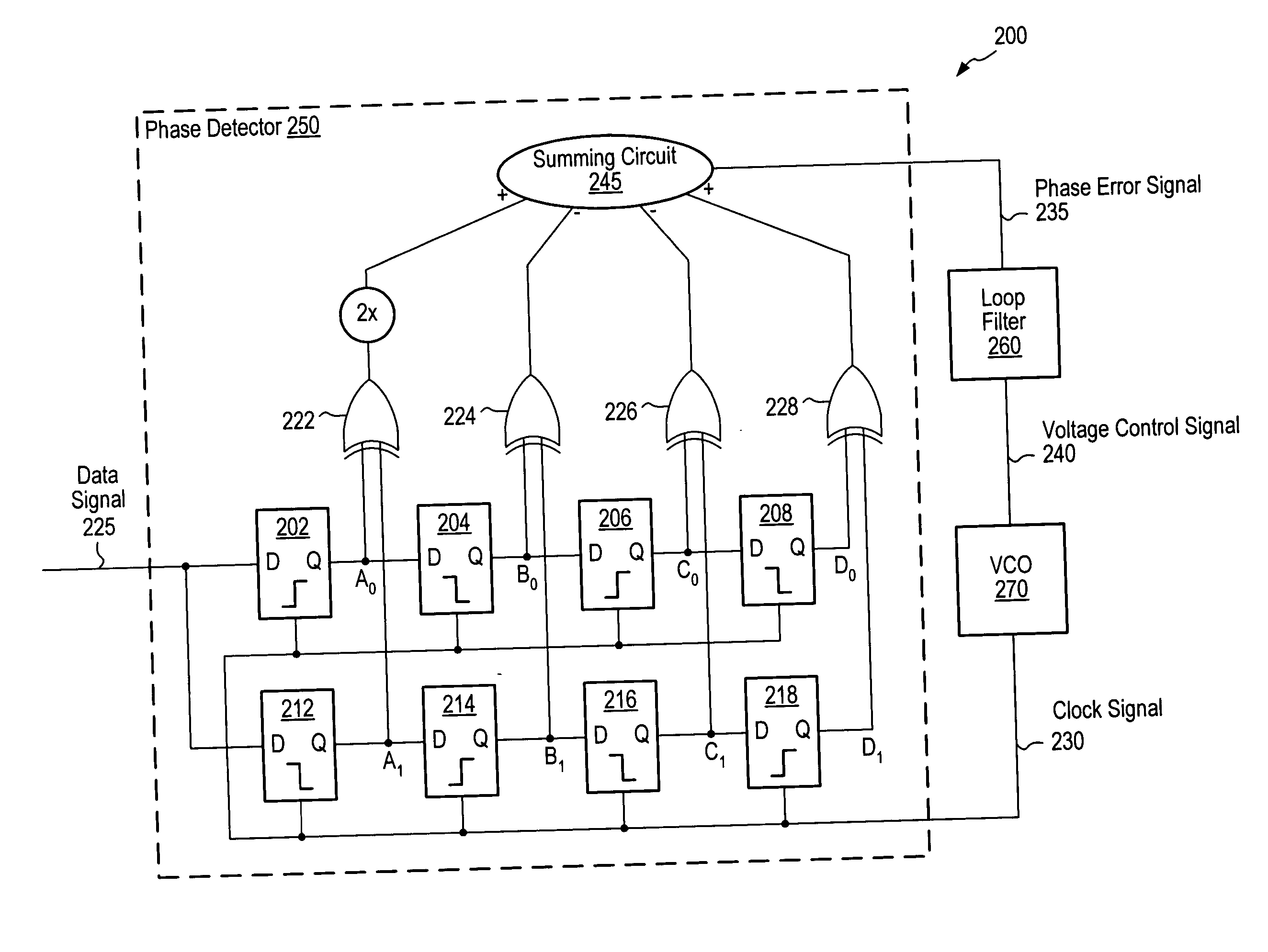
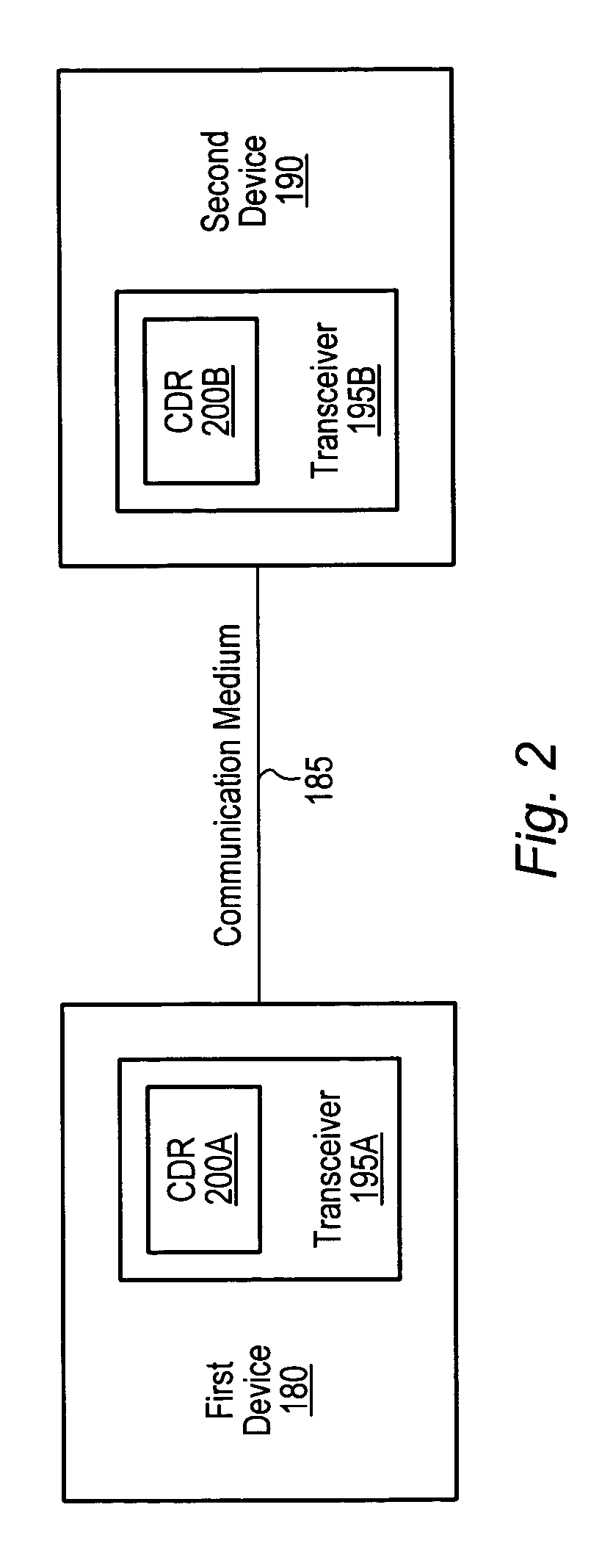
[0027]FIG. 2 is a block diagram of one embodiment of a communication system comprising a first device 180 and a second device 190, each including a linear, half-rate clock and data recovery (CDR) circuit 200. Each of the half-rate CDR circuits 200A and 200B may be included in an integrated circuit (IC), for example, a digital IC. In one embodiment, the half-rate CDR 200A may be comprised in a transceiver 195A of the first device 180, and the half-rate CDR 200B may be comprised in a transceiver 195B of the second device 190. The transceivers 195A and 195B may be configured to transmit and receives information (e.g., digital signals) via communication medium 185, such as a PCI Express bus. It is noted however that in other embodiments the half-rate CDRs may be used in transceivers to communicate via other types of communication standards, such as Serial ATA, USB, IEEE 1394, or Ethernet, among others.

[0028] The first and second devices 180 and 190 may be any of numerous types of devic...


PUM


Abstract

A linear, half-rate clock and data recovery (CDR) circuit for recovering clock information embedded in a received data signal. The half-rate CDR circuit comprises a phase detector that may receive the data signal and generate a phase error signal representative of the phase difference between the received data signal and a clock signal produced by a voltage-controlled oscillator (VCO) of the CDR circuit. The half-rate CDR typically changes the frequency of the clock signal and generates a clock signal that is aligned with the baud center of the received data signal. More specifically, when the half-rate CDR circuit is in a locked condition, both the rising and falling edges of the clock signal are aligned with the baud center of the received data signal. The half-rate CDR preferably generates a clock signal with an average frequency that is half the data rate of a received data signal.

Description

BACKGROUND OF THE INVENTION [0001] 1. Field of the Invention [0002] This invention relates generally to the field of digital interface design and, more particularly, to linear half-rate clock and data recovery (CDR) circuits. [0003] 2. Description of the Related Art [0004] Designers usually embed clock information in transmitted data signals to meet greater bandwidth requirements in a reduced area. Information signals including only binary data without separate clock signals (i.e., the clock information is embedded in the data) may require only half the bandwidth for transmission when compared to the bandwidth that may be required to transmit information signals including separate data and clock signals. Since the clock information in data signals is preferably embedded in the data, transceivers typically include clock and data recovery (CDR) circuits to recover the embedded clock information of a received data signal to decode the data. Thus, CDR circuits typically perform critical...

Claims


Application Information

Patent Timeline
IPC IPC(8): H03D3/24
CPCH04L7/033H03D13/003
Inventor BRIONES, LUIS J.
Owner MICROCHIP TECH INC
Why Eureka
Try Eureka