Optical device and method for the spectrally-designed attenuation of a multi-wavelength light signal

a multi-wavelength light signal and optical device technology, applied in the field of optical devices, can solve the problems of significant power fluctuations, special waveguide design and fabrication, and important problems, and achieve the effects of improving the tilt of wavelength dependent loss, increasing the attenuation range, and reducing insertion loss and attenuation rippl

Inactive Publication Date: 2006-03-23
UNIV LAVAL
View PDF3 Cites 20 Cited by
  • Summary
  • Abstract
  • Description
  • Claims
  • Application Information

AI Technical Summary

Benefits of technology

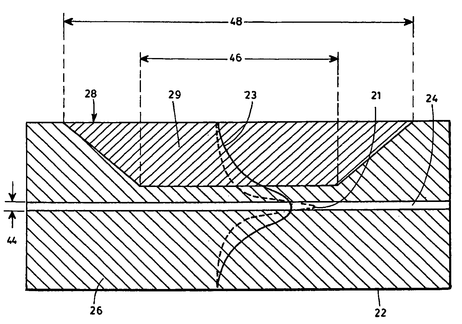
[0021] In a first embodiment of the invention, the principle of the present invention is applied to a VOA obtained by a simple cladding removing approach providing a design geometry of a standard linear optical waveguide (fiber, planar guide, etc.) with partially removed cladding that is replaced by a specific composite material mixture, which provides controllable optical loss improving the tilt of the wavelength dependent loss (the value of WDL).
[0022] This waveguide includes a cladding area, which is adiabatically removed with geometrical parameters (length, depth, slopes) that increase the attenuation range, reduce the insertion loss and the attenuation ripple due to multiple interference phenomena between core and cladding modes and their back coupling into the core in up tapered region of the removed cladding that is covered with a composite material mixture.
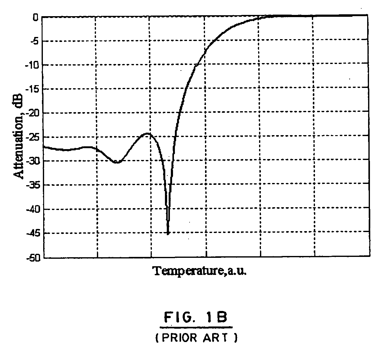
[0027] It should be noted that the choice of the guest particle's material composition, diameter and concentration may bring to the formation of optical non-uniformities of refractive index and / or absorption of the composite matrix, which in turn, may attenuate light via scattering, spatially non-uniform leakage and absorption, etc. with the desired spectral properties. For example, the so-called, Rayleigh scattering typically has λ−4 wavelength dependence, which obviously would increase the losses for shorter wavelengths. In another example, the introduced non-uniformities may generate effective portions of the controllable cladding that may create “multiple” zones of VOA with similar but mutually shifted transfer functions (attenuation versus control parameter, e.g., temperature) flattening thus the corresponding spectral dependence of the integral device.
[0029] Alternatively, the parameters of the guest compound and of the guide's geometry may be chosen in a way to generate higher losses for “red” wavelengths along with the increase of the nav, which will even more accentuate the existing tilt in the WDL. That is why we shall further understand a “spectral control” (that may provide both positive and negative slopes) when speaking about the WDL improvement.

Problems solved by technology

The energy budget and its dynamic balance are key issues to optimize the performance of agile optical telecommunication networks.
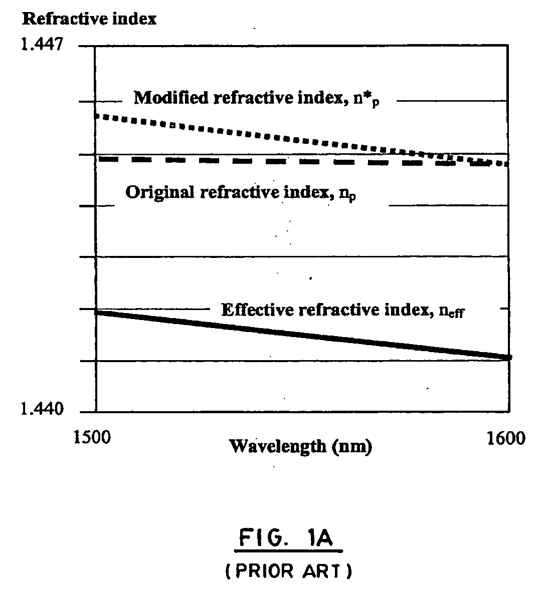
However, an important problem persists with these materials, which is related to their dispersion (refractive index dependence upon light wavelength: n(λ)).
The problem is particularly important when multiple channels (for example, in the conventional C band) are propagating in the same device.
Then the dynamic adding or dropping of a part of those channels brings to significant power fluctuations.
However, these approaches require a special waveguide design and fabrication, which is rather complicated and costly.
As we shall disclose below, the use of a non-uniform composite material as a part of cladding or the deformation of that axes may decrease the wavelength dependence of attenuation.
First one is the problem of the chemical miscibility and stability of the organic dye-polymer composition.
Another problem is related to the fact that the limited group of known dyes, which offer the “flattening” capacity, is composed of big organic molecules.
Such molecules are rather unstable from photochemical point of view, in particularly when using multiple cycles of thermal control.
The third problem is related to the additional optical losses introduced by those dyes at working telecommunication wavelengths (1300-1600 nm).
Finally the high cost of the dye and the difficulty of its uniform integration in the polymer matrix (without aggregation or precipitation) complete the list of drawbacks of this approach.
In summary, the methods described above remain complex, non-reliable and costly.

Method used


Image

  • Optical device and method for the spectrally-designed attenuation of a multi-wavelength light signal
  • Optical device and method for the spectrally-designed attenuation of a multi-wavelength light signal
  • Optical device and method for the spectrally-designed attenuation of a multi-wavelength light signal

Examples


example

[0088] 0.050 g of 1.1 micron sized polybeads polystyrene microsphere in powder form was dispersed as guest in a 1 g fluorinated polymer thermo-optic (TO) host matrix. The mixture allows to stirring at 25° C. for 2 h. The mixture was used as a cladding material for an optical fiber of partially removed cladding. The reduction of the cladding was made by a local chemical etching. The light propagating in the optical fiber, that contains the mixture as cladding, was leaking out from the core because of the high average refractive index of the composite material at room temperature. The heating of the composite material (TO material with PS microspheres) brings to a gradual increase of light transmission achieving an insertion loss below 0.2 dB. The wavelength dependent loss (WDL) of such a device appears to be greatly improved (below 0.5 dB) with respect to the case when only the original TO polymer is used without the PS microsphere.

[0089] In summary, the present invention addresses ...


PUM


Abstract

A device and method for the spectrally-designed and controlled attenuation of a light signal, including an attenuation structure which may be placed in the proximity of a waveguide's core and which comprises a base material system containing non-uniformities having optical properties that are different from those of the host. These non-uniformities may have various natures, geometrical forms and sizes and may be created, doped or otherwise introduced in the base material system to obtain externally controllable optical properties of the whole composite material providing a broadband spectral performance.

Description

FIELD OF THE INVENTION [0001] The present invention relates to the field of optical devices and more particularly concerns the design and control of the spectral dependence of the attenuation of a multi-wavelength light signal. BACKGROUND OF THE INVENTION [0002] The energy budget and its dynamic balance are key issues to optimize the performance of agile optical telecommunication networks. This requires the use of variable optical attenuators (VOAs). At the same time, an optical telecommunication line needs more optical amplifiers if the optical losses of the network are high. It is therefore very important to choose optical components (e.g., VOAs) with minimal losses when they are used in their transparent state. The in-guide (or guided wave) modulation of light propagation (light remains in the original waveguide while being transformed) appears to be the best solution for the fabrication of low-loss optical components. The main underlying principle here is the use of the evanesce...

Claims


Application Information

Patent Timeline
Patent Type & Authority Applications(United States)
IPC IPC(8): G02B6/26
CPCB82Y10/00G02B6/266B82Y20/00
Inventor GALSTIAN, TIGRANZOHRABYAN, ARMENTORK, AMIRBIRABASSOV, ROUSLAN
Owner UNIV LAVAL
Why Eureka
Try Eureka