

Organic electroluminescent material and organic electroluminescent device by using the same
a technology of electroluminescent devices and electroluminescent materials, which is applied in the direction of luminescent screens for discharge tubes, organic chemistry, natural mineral layered products, etc., can solve the problem of not being easily degraded, and achieve the effect of low luminescent efficiency
- Summary
- Abstract
- Description
- Claims
- Application Information
AI Technical Summary
Benefits of technology
Problems solved by technology
Method used
Image

Examples
first embodiment
[0025] An organic electroluminescent material according to a first preferred embodiment of the invention has the structure of the following formula (1): [0026] wherein A and B are an electron donating group, R1 and R2 are an alkyl group.
[0027] In this embodiment, A and B are one selected from the group consisting of a substituted amino group having 1 to 30 carbon atoms, a non-substituted amino group having 1 to 30 carbon atoms, an alkoxy group having 1 to 10 carbon atoms, and an aroxy group having 1 to 30 carbon atoms.
[0028] R1 and R2 are one selected from the group consisting of a substituted alkyl group having 1 to 6 carbon atoms and a non-substituted alkyl group having 1 to 6 carbon atoms.
[0029] In addition, R1 can bond with A. Alternatively, R2, of course, can bond with A, too.
[0030] For instance, the organic electroluminescent material of this embodiment can be but not limited to one compound of the following formulas:
second embodiment
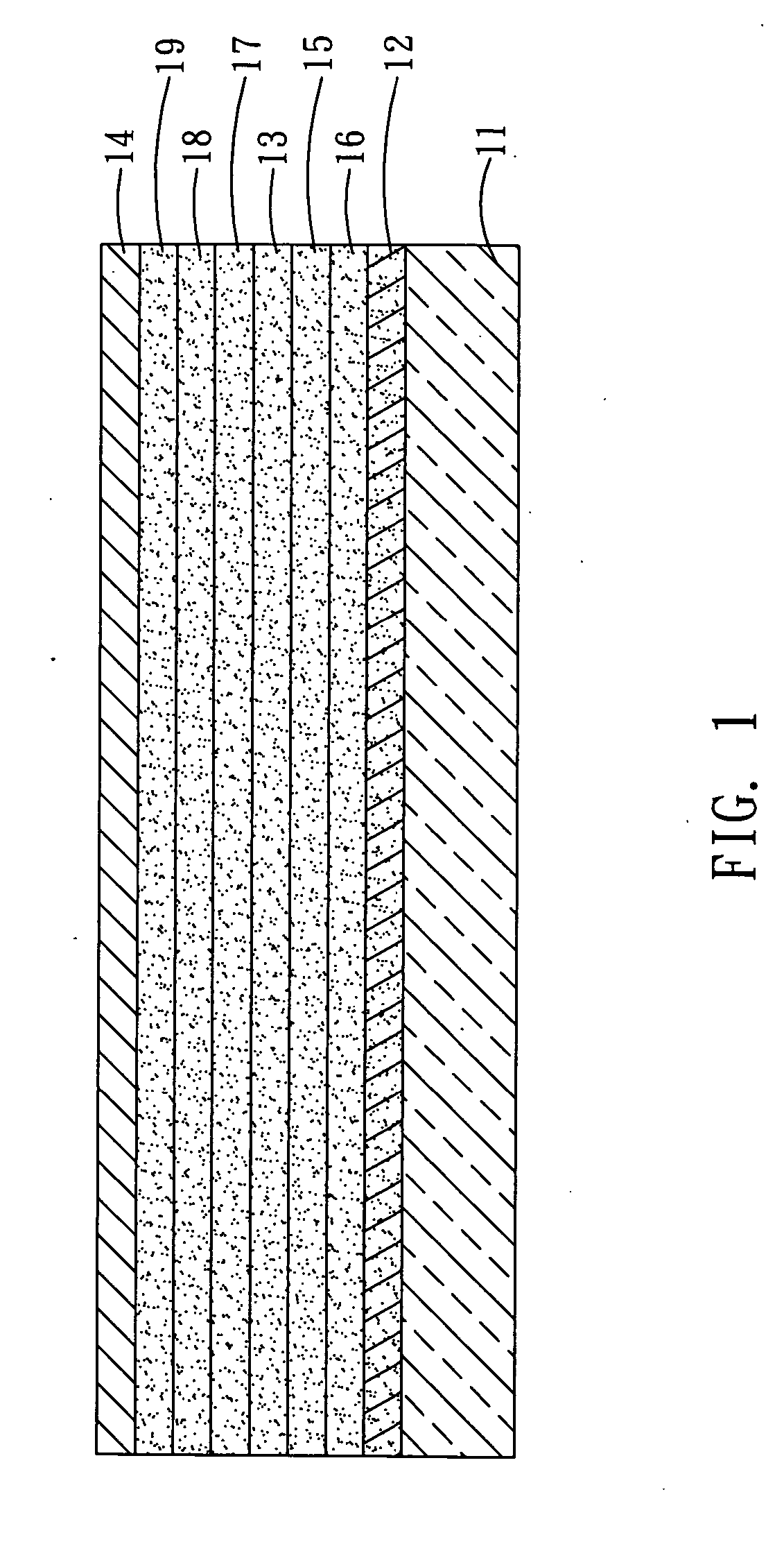
[0031] With reference to FIG. 1, an organic electroluminescent device 1 according to a second preferred embodiment of the invention comprises a first electrode 12, a light-emitting layer 13 and a second electrode 14 disposed over the substrate 11 in sequence. The light-emitting layer 13 comprises an organic electroluminescent material of the following formula (2): [0032] wherein A′ and B′ are an electron donating group, R1′ and R2′ are an alkyl group.
[0033] In the second embodiment, A′ and B′ are one selected from the group consisting of a substituted amino group having 1 to 30 carbon atoms, a non-substituted amino group having 1 to 30 carbon atoms, an alkoxy group having 1 to 10 carbon atoms, and an aroxy group having 1 to 30 carbon atoms.
[0034] R1′ and R2′ are one selected from the group consisting of a substituted alkyl group having 1 to 6 carbon atoms and a non-substituted alkyl group having 1 to 6 carbon atoms.
[0035] In addition, R1′ can bond with A′. Alternatively, R2′, of...
example 1
[0059]
[0060] This example illustrates a synthesis method of the organic electroluminescent material according to the embodiment of the invention.
Compound 2: 7-Diethylamino-3-(4-methoxy-phenyl)-chromen-2-one
[0061] First, 4-Diethylamino-2-hydroxy-benzaldehyde (2.000 g, 10.35 mmol), (4-Methoxy-phenyl)-acetic acid methyl ester (1.864 g, 10.35 mmol), and Piperidine (0.881 g, 10.35 mmol) are added into a two-neck bottle. One neck of the two-neck bottle is injected with hydrogen, and the other neck thereof is sealed with a serum plug. After that, 20.0 ml acetonitrile is added, and the solution is then stirred, heated and refluxed for 24 hours. After the temperature of the solution is recovered, ice water is then added to quench the reaction. The solution is extracted by ethyl acetate for several times. The organic layer of the extracted solution is collected and dehydrated by MgSO4, and then purified by the silica gel column chromatography (mobile phase: EA / n-Hexane=0.2) to obtain a yell...
PUM
| Property | Measurement | Unit |
|---|---|---|
| luminance | aaaaa | aaaaa |
| luminescent wavelength | aaaaa | aaaaa |
| luminance | aaaaa | aaaaa |
Abstract
Description
Claims
Application Information