Hybridization detecting unit relying on dielectrophoresis, sensor chip provided with the detecting unit, and method for detection of hybridization

a detection unit and dielectrophoresis technology, applied in the field of hybridization detection, can solve the problems of difficult detection difficulty in accurately determining the amount and low probability of target nucleic acids meeting complementary nucleic acids for detection, so as to reduce steric hindrance, reduce mishybridization, and increase the probability of hybridization

Inactive Publication Date: 2006-03-23
SONY CORP
View PDF8 Cites 32 Cited by
  • Summary
  • Abstract
  • Description
  • Claims
  • Application Information

AI Technical Summary

Benefits of technology

[0037] The present invention is designed to compulsorily move by dielectrophoresis the target nucleic acid to the region in which the nucleic acid for detection is fixed. Movement in this way increases the probability that hybridization takes place. In addition, dielectrophoresis elongates the nucleic acid molecules, thereby reducing steric hindrance detrimental to hybridization or reducing mishybridization.

Problems solved by technology

The disadvantage of the conventional DNA chip technology is that the probability of the target nucleic acid meeting its complementary nucleic acid for detection is very low under the natural condition in which Brownian motion is the only driving force.
This presents difficulties in detecting the target nucleic acid or difficulties in accurately determining the amount of the target nucleic acid even though the detection of the target nucleic acid is possible.

Method used


Image

  • Hybridization detecting unit relying on dielectrophoresis, sensor chip provided with the detecting unit, and method for detection of hybridization
  • Hybridization detecting unit relying on dielectrophoresis, sensor chip provided with the detecting unit, and method for detection of hybridization
  • Hybridization detecting unit relying on dielectrophoresis, sensor chip provided with the detecting unit, and method for detection of hybridization

Examples


first embodiment

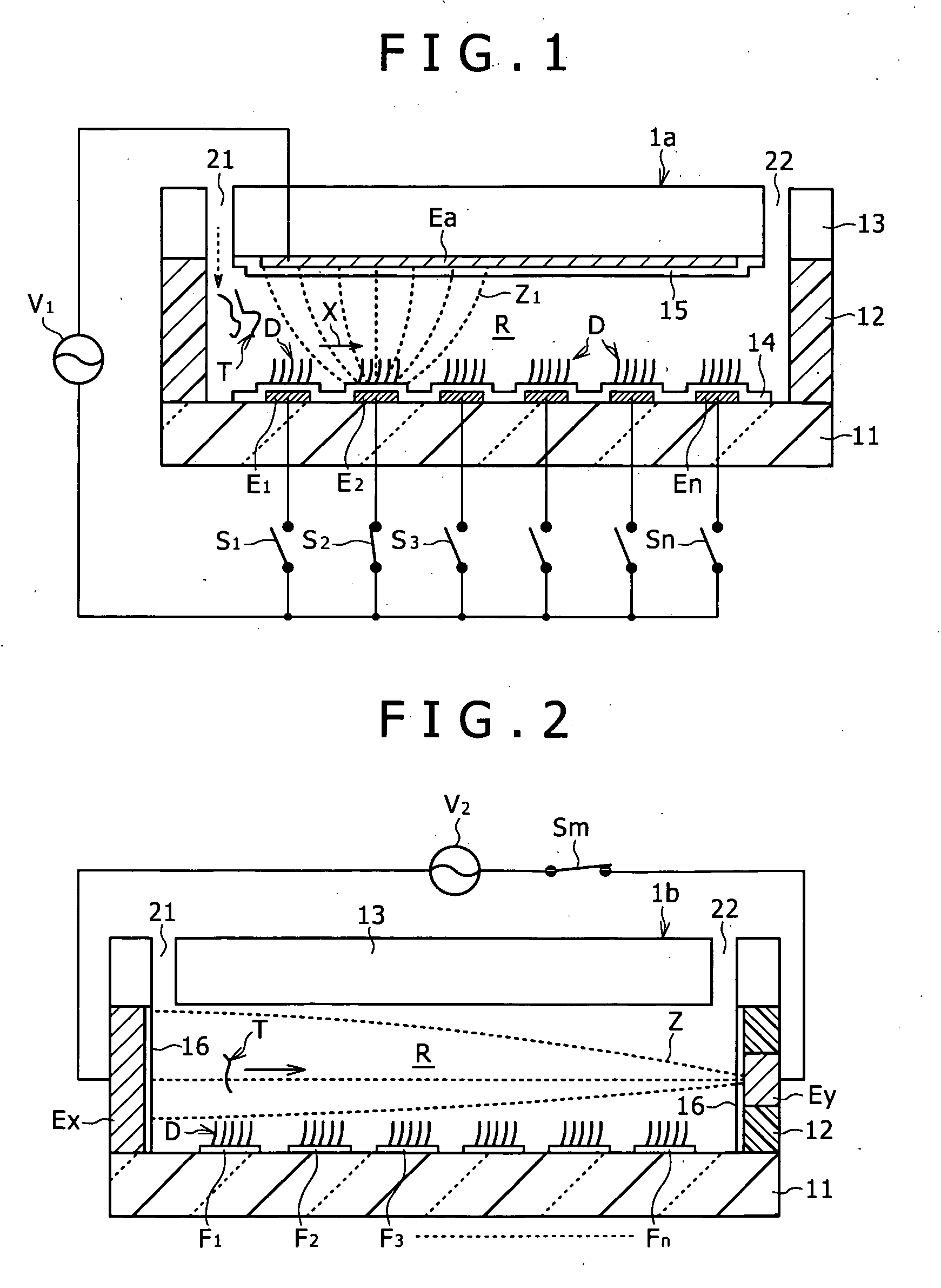
[0052] FIGS. 1 to 10 are diagrams illustrating the detecting unit pertaining to the preferred embodiments of the present invention. The substrate structure common to all the embodiments will be described with reference to FIG. 1 which is a vertical sectional view showing the detecting unit according to the present invention.

[0053] The substrate that can be used in the present invention may be formed from the same material as used for optical information recording media, such as CD (Compact Disc), DVD (Digital Versatile Disc), and MD (Mini Disc). In addition, the substrate used in the present invention is not specifically restricted in its shape; it may assume any shape such as disc and rectangle depending on the object of their use.

[0054] The underlying substrate 11 (the lowermost layer) shown in FIG. 1 is formed from transparent silica glass or transparent synthetic resin (such as silicone, polycarbonate, and polystyrene). A synthetic resin capable of injection molding is desirabl...

second embodiment

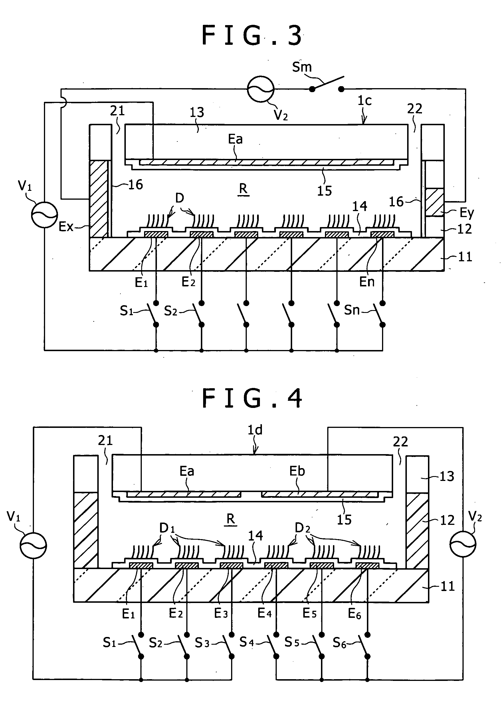
[0082] The detecting unit according to the present invention will be described below with reference to FIG. 2.

[0083] The detecting unit (indicated by symbol 1b) in FIG. 2 differs in construction from the detecting unit 1a according to the first embodiment such that the fixing sites indicated by symbols F1 tos Fn are not electrodes and the reaction region (R) is provided with opposing electrodes Ex-Ey at its right and left sides (Compare FIG. 1 with FIG. 2).

[0084] The detecting unit 1b produces an electric field that extends from left to right along the fixing sites F1 to Fn when an electric field is applied to the opposing electrodes Ex-Ey. If either of the opposing electrodes is made smaller than the other, an uneven electric field is produced in the vicinity of the smaller electrode (Ey, in this case). Incidentally, symbol Z in FIG. 2 schematically shows the line of electric force due to such an uneven electric field.

[0085] The target nucleic acid T, which is present in a free s...

third embodiment

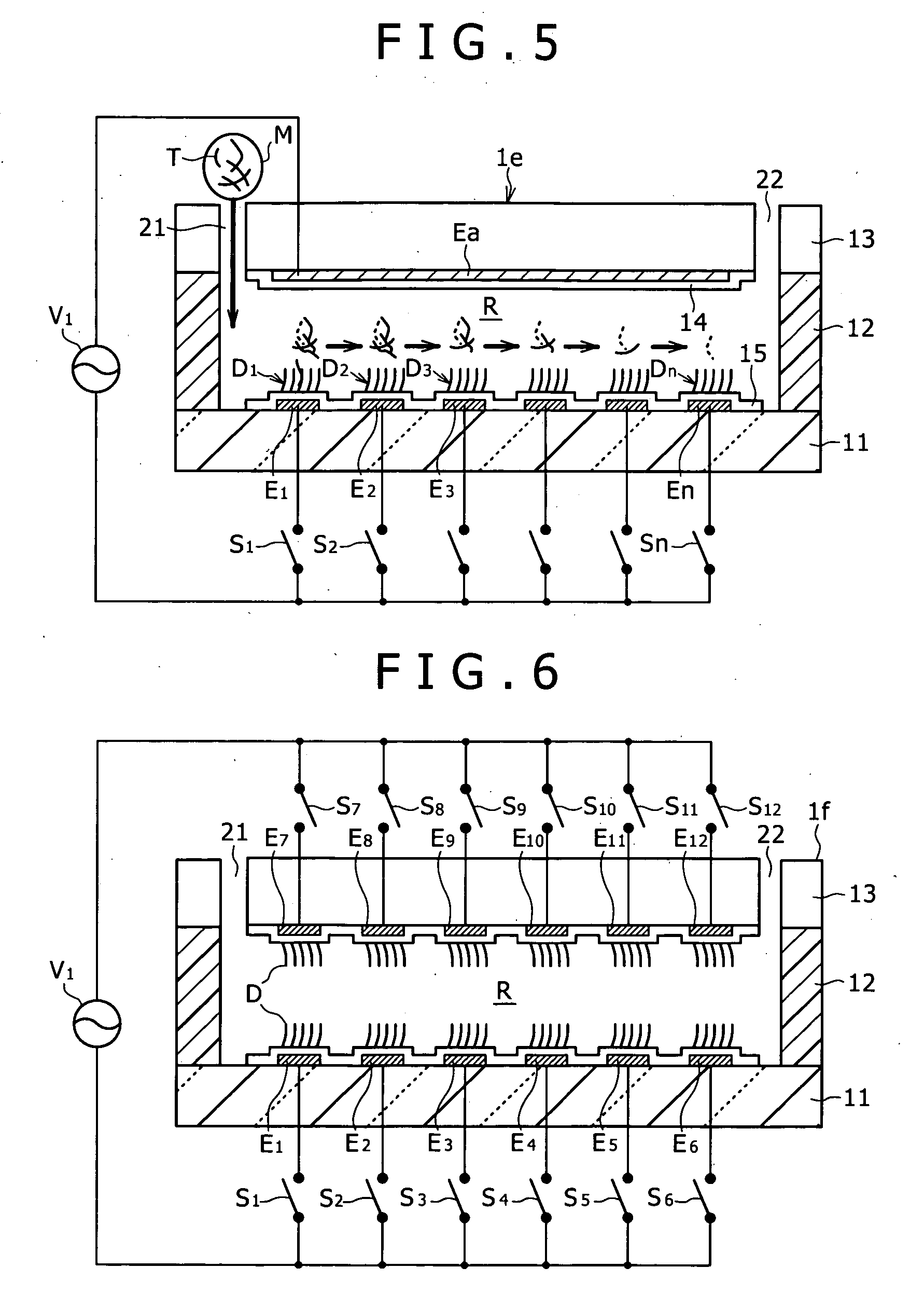
[0086] The detecting unit according to the present invention will be described below with reference to FIG. 3.

[0087] The detecting unit 1c shown in FIG. 3 is characterized in that it has the opposing electrodes E1-Ea, to En-Ea, which are arranged above and below the reaction region (R), and the opposing electrodes Ex-Ey, which are arranged at right and left of the reaction region (R). The detecting unit 1c is, so to speak, a combination of the detecting unit 1a shown in FIG. 1 and the detecting unit 1b shown in FIG. 2.

[0088] The advantage of the detecting unit 1c is that the target nucleic acid T is moved to the vicinity of the desired position by application of an electric field to the opposing electrodes Ex-Ey and then attracted to the vicinity of the electrodes E1 to En by application of an electric field to the opposing electrodes E1-Ea to En-Ea. Another advantage is that the opposing electrodes Ex-Ey may be used to eliminate any substance detrimental to hybridization and nucle...


PUM

PropertyMeasurementUnit
electric fieldaaaaaaaaaa
insulatingaaaaaaaaaa

Abstract

A hybridization detecting unit which includes a reaction region in which hybridization takes place, a plurality of sites (e.g., the surface of electrodes) arranged in the reaction region to which is fixed a nucleic acid for detection, and means for sequentially moving by dielectrophoresis the target nucleic acid introduced into the reaction region according to the order of arrangement of the sites to which is fixed a nucleic acid for detection. A sensor chip provided with the hybridization detecting unit. The detecting unit compulsorily moves the target nucleic acid into the region where a probe nucleic acid for detection exists, thereby increasing the probability of hybridization taking place.

Description

BACKGROUND OF THE INVENTION [0001] The present invention relates to a technique to detect hybridization. More particularly, the present invention relates to a technique to detect hybridization which is so designed as to move by dielectrophoresis a target nucleic acid to a site where a nucleic acid for detection is fixed. [0002] It has recently become common practice to use an integrated substrate for bioassay which has DNA molecules of prescribed species minutely arranged thereon by microarray technology. The integrated substrate, which is called DNA chip or DNA microarray (the former terminology is used in the present invention), is used to analyze gene mutation, SNPs (simple nucleotide polymorphism), and gene expression frequency. It will find use in broad areas including drug development, clinical diagnosis, pharmacogenomics, evolution research, and legal medicine. [0003] The DNA chip is a glass substrate or silicon substrate on which are integrated a variety of and a large numbe...

Claims


Application Information

Patent Timeline
Patent Type & Authority Applications(United States)
IPC IPC(8): C12Q1/68C12M1/34
CPCB03C5/005B03C2201/26B03C2201/24B03C5/026
Inventor SEGAWA, YUJIKISHII, NORIYUKI
Owner SONY CORP
Why Eureka
Try Eureka