
Magnetic recording medium and method for manufacturing the same

a magnetic recording medium and manufacturing method technology, applied in the field of magnetic recording medium manufacturing method, can solve the problems of reducing the size of magnetic elements, ferromagnetism will disappear due to thermal fluctuations, and transition noise becomes a problem, so as to reduce the noise of transition, prevent the aggregation of magnetic particles, and high productivity

Inactive Publication Date: 2006-03-30
FUJIFILM CORP +1
View PDF5 Cites 9 Cited by
  • Summary
  • Abstract
  • Description
  • Claims
  • Application Information

AI Technical Summary

Benefits of technology

[0009] The present invention has been made in view of the above circumstances and provides a magnetic recording medium and a manufacturing method thereof which reduces transition noise whilst preventing aggregation of magnetic particles, and which has high productivity.

Problems solved by technology

The following points are problems when increasing the density of magnetic recording media.
First, for high density recording, whilst it has become possible to make the size of magnetic elements small, there is a fear that with a reduction in the size of the magnetic elements that ferromagnetism will disappear due to thermal fluctuations.
Also, along with increasing the recording density, transition noise becomes a problem.
However, since this type of magnetic body is nonmagnetic or soft magnetic at the time of synthesis, in order to make it in a hard magnetic usually it is necessary to carry out an annealing process at over 500° C. Because of this, at the stage of carrying out annealing at high temperature the particles themselves tend to fuse together and make large particles, and hence the fundamental goal of reducing the size of the particles cannot be achieved.
However, this mode is considered to be disadvantageous to the traversing of a flying head due to projections being formed on the surface.
The thin layer formed on the projected portions is removed along with the removal of the mask pattern, and so there is the problem that it is disadvantageous in terms of productivity.

Method used


Image

  • Magnetic recording medium and method for manufacturing the same
  • Magnetic recording medium and method for manufacturing the same
  • Magnetic recording medium and method for manufacturing the same

Examples


example 1

Preparation of FePt Alloy Particles

[0183] The process as shown below was performed in high purity N2 gas.

[0184] To a reducing agent aqueous solution containing 0.76 g of NaBH4 (manufactured by Wako Pure Chemical Industries Ltd.) dissolved in 16 ml of water (deoxygenated to 0.1 mg / l or below) was added an alkane solution of a mixture of 10.8 g of Aerosol OT (manufactured by Wako Pure Chemical Industries Ltd.), 80 ml of decane (manufactured by Wako Pure Chemical Industries Ltd.), and 2 ml of oleyl amine, mixed and a reverse micelle solution (I) was thereby prepared.

[0185] To a metal salt aqueous solution containing 0.46 g of iron triammonium trioxalate (Fe(NH3)3(C2O4)3) (manufactured by Wako Pure Chemical Industries Ltd.), and 0.38 g of potassium platinum chloride (K2PtCl4) (manufactured by Wako Pure Chemical Industries Ltd.) dissolved in 12 ml of water (deoxygenated) was added an alkane solution of 5.4 g of Aerosol OT (manufactured by Wako Pure Chemical Industries Ltd.) mixed wit...


PUM

PropertyMeasurementUnit
particle diameteraaaaaaaaaa
temperatureaaaaaaaaaa
widthaaaaaaaaaa

Abstract

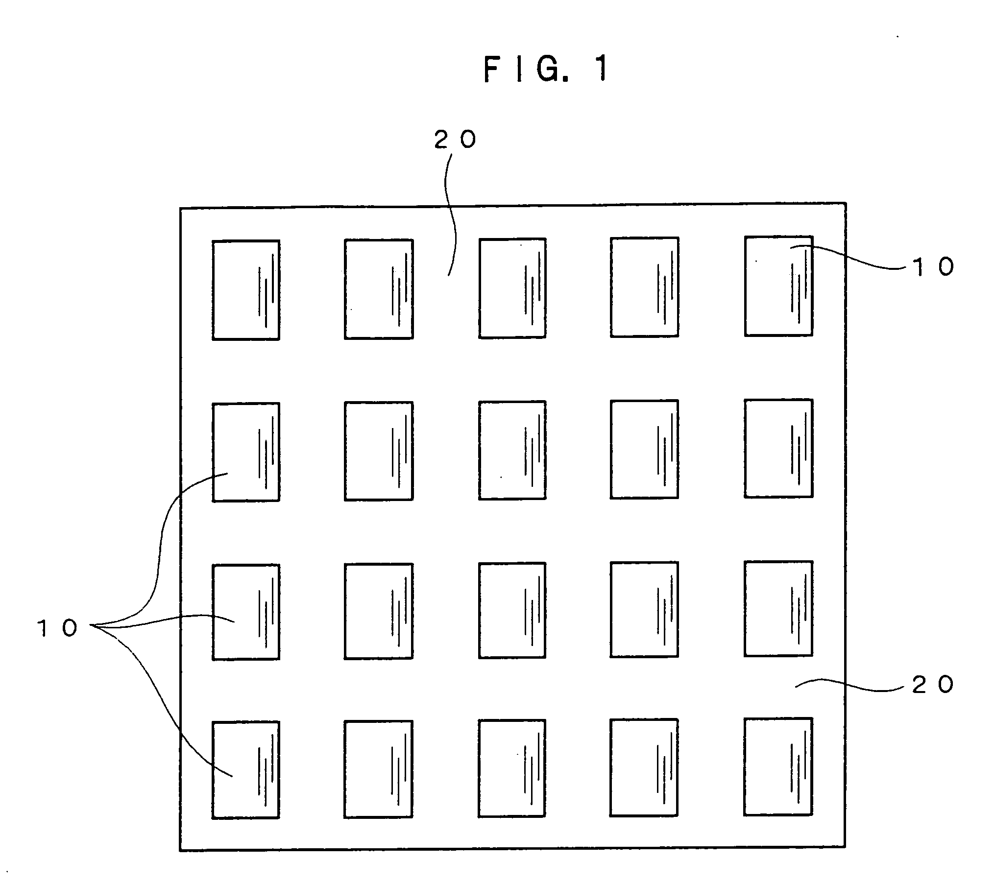
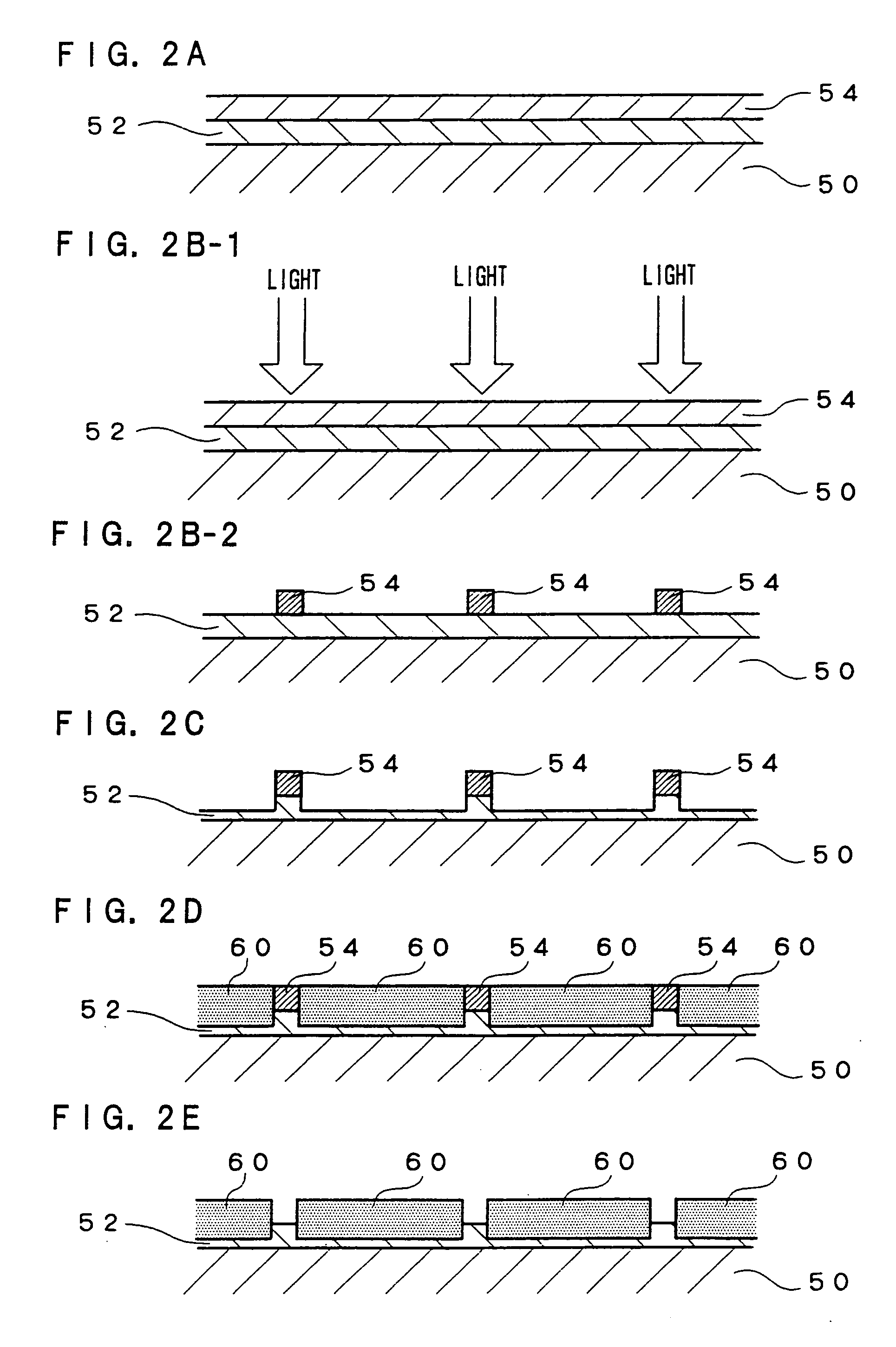
The invention is a magnetic recording medium which contains magnetic regions and non-magnetic regions. There are two or more of the magnetic regions with each of the regions containing a ferromagnetic ordered alloy, of either a CuAu-type or Cu3Au-type, and a matrix agent, and each of the magnetic regions is formed as a physically separate shape. The invention also includes a manufacturing method for manufacturing the magnetic recording medium which comprises forming magnetic regions using a mask which uses a photopolymer to form the magnetic regions containing the ferromagnetic ordered alloy, of either a CuAu-type or Cu3Au-type, and the matrix agent.

Description

CROSS-REFERENCE TO RELATED APPLICATION [0001] This application claims priority under 35 USC 119 from Japanese Patent Application No. 2004-288560, the disclosure of which is incorporated by reference herein. BACKGROUND OF THE INVENTION [0002] 1. Field of the Invention [0003] The present invention relates to a manufacturing method for a magnetic recording medium, and in particular to a magnetic recording medium of a so called patterned media and a manufacturing method thereof. [0004] 2. Description of the Related Art [0005] The following points are problems when increasing the density of magnetic recording media. First, for high density recording, whilst it has become possible to make the size of magnetic elements small, there is a fear that with a reduction in the size of the magnetic elements that ferromagnetism will disappear due to thermal fluctuations. Also, along with increasing the recording density, transition noise becomes a problem. [0006] It has been proposed to use CuAu-ty...

Claims


Application Information

Patent Timeline
Patent Type & Authority Applications(United States)
IPC IPC(8): G11B5/65B05D5/12
CPCB82Y25/00B82Y40/00G11B5/706G11B5/70615G11B5/70621H01F1/0054G11B5/855H01F1/065H01F41/301H01F10/123G11B5/714
Inventor HATTORI, YASUSHI
Owner FUJIFILM CORP
Learn More