Valve for vacuum exhaustion system

a vacuum exhaustion and valve technology, applied in the direction of engine diaphragms, diaphragm valves, valve housings, etc., can solve the problems of clogging and leakage of valve seats, water, moisture and gases condense in corrosion of materials, etc., to reduce the diameter of the vacuum exhaustion piping, reduce the cost, and facilitate the effect of the vacuum exhaustion system

Active Publication Date: 2006-04-06
FUJIKIN INC +1
View PDF13 Cites 11 Cited by
  • Summary
  • Abstract
  • Description
  • Claims
  • Application Information

AI Technical Summary

Benefits of technology

[0011] It is a primary object of the present invention to provide a valve which makes it possible to reduce the diameter of the vacuum exhaustion pipings for making the facility for the vacuum exhaustion system small-sized, lowering the costs, and making the vacuum exh

Problems solved by technology

However, in the event that the pressure is increased as such, there is a possibility that water, moisture and gases condense in the vacuum exhaustion system and adhere inside the pipings.
Even if the condensation and adherence of water, moisture caused by the set pressure rise do not occur, the dissociation (decompositi

Method used


Image

  • Valve for vacuum exhaustion system
  • Valve for vacuum exhaustion system
  • Valve for vacuum exhaustion system

Examples


Embodiment Construction

[0061] The embodiment in accordance with the present invention is described hereunder with reference to the drawings.

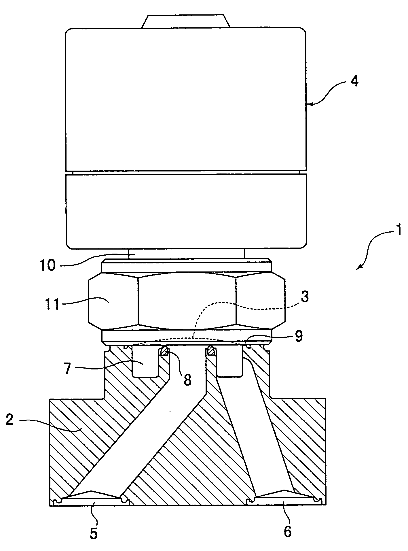
[0062]FIG. 5 is a vertical sectional view of the valve in accordance with the present invention, which is a type of valve called a metal diaphragm valve.

[0063] A major part of the metal diaphragm valve 1 comprises a body 2, a metal diaphragm 3 and a driving means 4.

[0064] The body 2 is provided with a valve seat 8 which is formed on the bottom face of a valve chamber 7 in communication with a flow-in passage 5 and a flow-out passage 6. The body 2 is made of aluminum, aluminum alloys and the like. The body 2 is further provided with a concave-shaped valve chamber 7 opened in the upward direction, a flow-in passage 5 opening downward and being in communication with the valve chamber 7, a flow-out passage 6 opening downward and being in communication with the valve chamber 7, a valve seat 8 made of synthetic resin and the like and fitted into and secured to the center...


PUM


Abstract

The present invention provides a valve which makes it possible to reduce the diameter of the vacuum exhaustion pipings for making the facility for the vacuum exhaustion system small, as a result lowering the costs, and making the vacuum exhaustion time short, and also which can prevent the corrosions, cloggings, and seal leakages inside the piping system caused by the accumulation of substances produced by the decomposition of the gas. Specifically, the aluminum passivation is applied on the piping parts, i.e. the valve and others, used in the vacuum exhaustion system to inhibit the gas decomposition caused by the temperature rise at the time of the baking so that components for the reduction in the diameter size in the vacuum exhaustion system are provided. The corrosions, cloggings and seat leakages caused by the gas decomposition are prevented.

Description

FIELD OF THE INVENTION [0001] The present invention is concerned with a valve to be used in the fluid control device and the like in the semiconductor manufacturing equipment. More particularly, the present invention is concerned with a valve to be used in the system for the exhaustion from the process chamber employed in the semiconductor manufacturing. BACKGROUND OF THE INVENTION [0002] Generally, a gas having high chemical reactivity is supplied to the process chamber used in the semiconductor manufacturing facilities, the chemicals manufacturing facilities and the like. Accordingly, the exhaustion system for the process chamber is required to exhaust high reactivity gases in safety and with a high degree of efficiency. [0003] Therefore, to conduct an efficient exhaustion from the process chamber, it is necessary to employ an exhaustion pump with a high compression ratio which can exhaust at a high exhaustion velocity (1 / min) even if the suction pressure is low. However, in reali...

Claims


Application Information

Patent Timeline
IPC IPC(8): F16K1/00H01L21/205F16K7/14F16K27/00F16K51/02
CPCF16K7/14F16K51/02F16K27/003F16K25/005F16K25/04H01L21/02
Inventor OHMI, TADAHIROIKEDA, NOBUKAZUYAMAJI, MICHIOKITANO, MASAFUMIMORIMOTO, AKHIRO
Owner FUJIKIN INC
Why Eureka
Try Eureka