Microwave sealing for radar level gauges

Inactive Publication Date: 2006-04-06
ROSEMOUNT TANK RADAR
View PDF23 Cites 18 Cited by
  • Summary
  • Abstract
  • Description
  • Claims
  • Application Information

AI Technical Summary

Benefits of technology

[0029] Further, it is preferred that the means for blocking electromagnetic energy provides a microwave attenuation of at least 10 dB, and most preferably at least 20 dB, as compared to the leakage with a conventional flange sealed material with low loss or no conductivity.
[0030] The means for blocking electromagnetic energy is preferably adapted to be located outside the pressure thight seal joint provided by the sealing unit in relation to the tank inside. In this way, the sealing unit faces the wet side of the tank, and thereby protects

Problems solved by technology

Typically there is a need to keep the tank well closed, due to pressure differences, risk for leakage, etc.
However, of the small microwave power used inside the tank a small fraction of it may escape from the tank and seen from the outside as emitted electro

Method used


Image

  • Microwave sealing for radar level gauges
  • Microwave sealing for radar level gauges
  • Microwave sealing for radar level gauges

Examples


Example

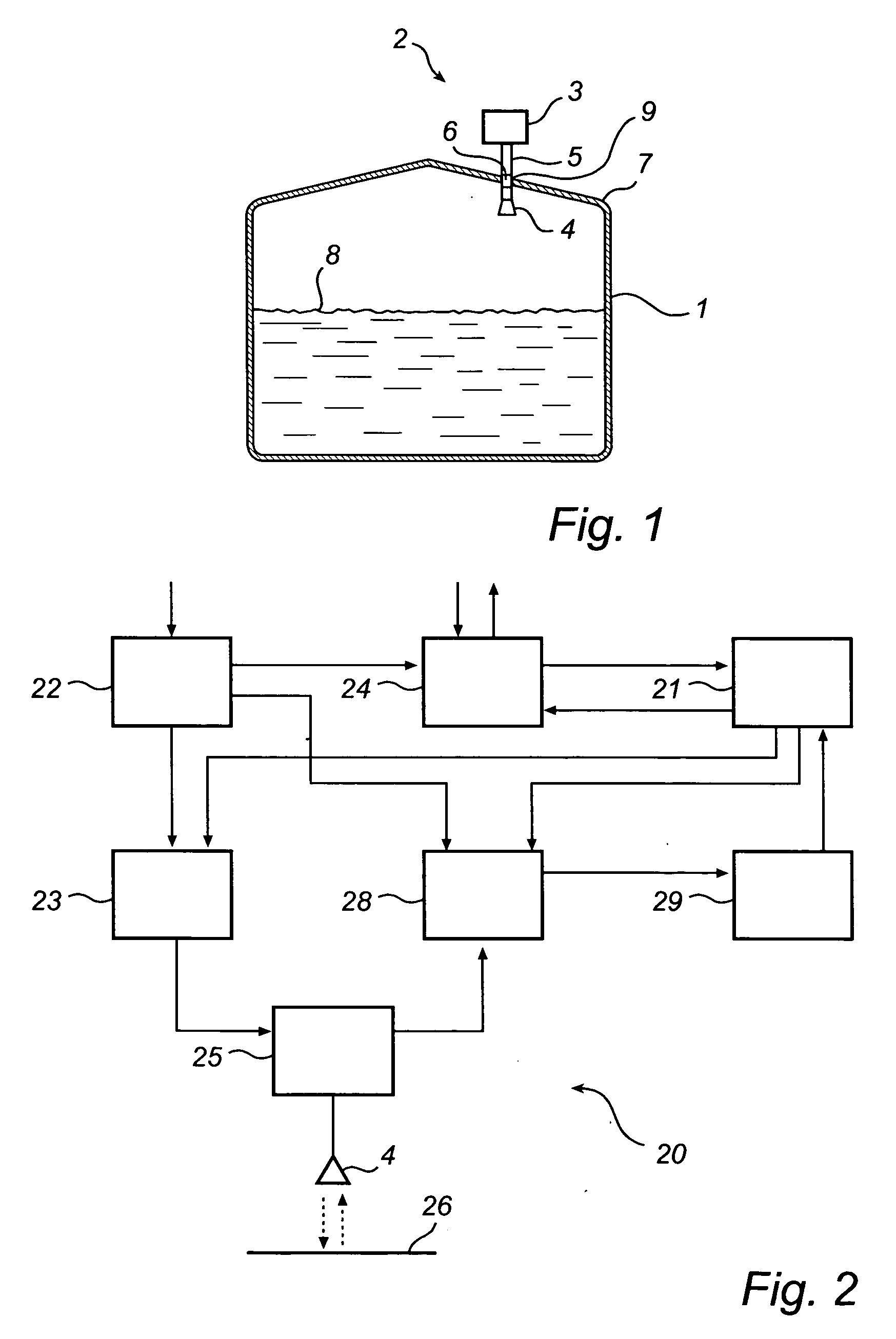
[0052]FIG. 1 shows schematically a tank 1 provided with a radar level gauge system 2. In brief, the system in FIG. 1 comprises an electronic unit 3 for transmitting and receiving radar signals and processing the received signals in order to determine the level in the tank, an antenna 4 arranged inside the tank for transmitting and receiving radar waves into the tank, and a radar wave guide assembly 5 for guiding signals between the electronic unit 3 and the antenna 4. In order to maintain temperature and pressure in the tank, and to protect the outside environment from the tank contents, a wave guide sealing 6 is arranged close to where the wave guide 5 passes through the tank wall 7 to provide sealing of the tank 1. The same antenna could preferably be used both as a transmitter for emitting the output radiation and as a receiver for receiving the reflected echo signal, even though it is also possible to use separate antennas for these functions.

[0053] In use, the radar level gaug...


PUM


Abstract

A radar level gauge system is disclosed, having a transmitter for transmitting measuring signals towards the surface of the filling material, a receiver for receiving echo signals from said surface and a fastening structure adapted to secure said transmitter and receiver in a measuring position on a feed-through structure located in an upper boundary of said container. Further, a sealing unit is arranged between said fastening structure and said feed-through, and adapted to provide a pressure seal between the inside and the outside of the container, and in addition, there is provided means for blocking electromagnetic energy, adapted to block net transfer of electromagnetic energy between the inside and the outside of the container through said sealing unit.

Description

FIELD OF THE INVENTION [0001] The present invention relates to a radar level gauge system for determining the filling level of a filling material in a tank. Such a system could comprise a transmitter for emitting measuring signals towards the surface of the filling material; a receiver for receiving echo signals from the tank; and processing circuitry for determining the filling level of the tank based on said echo signal. In particular, the invention is concerned with the sealing at a flange on the tank and especially at the opening where the radar level gauge is located. BACKGROUND OF THE INVENTION [0002] Measuring the level of a liquid, fluids, granular compounds or other materials stored in a tank is a basic industrial need. Several technologies have historically been employed and the last decade radar has emerged as the dominating method for high quality measurements. These devices utilize antennas to transmit electromagnetic waves toward the material being monitored and to rec...

Claims


Application Information

Patent Timeline
IPC IPC(8): G01S13/08
CPCG01F23/284G01S13/88
Inventor EDVARDSSON, OLOV
Owner ROSEMOUNT TANK RADAR
Why Eureka
Try Eureka