Deflecting magnetic field shield
- Summary
- Abstract
- Description
- Claims
- Application Information
AI Technical Summary
Benefits of technology
Problems solved by technology
Method used
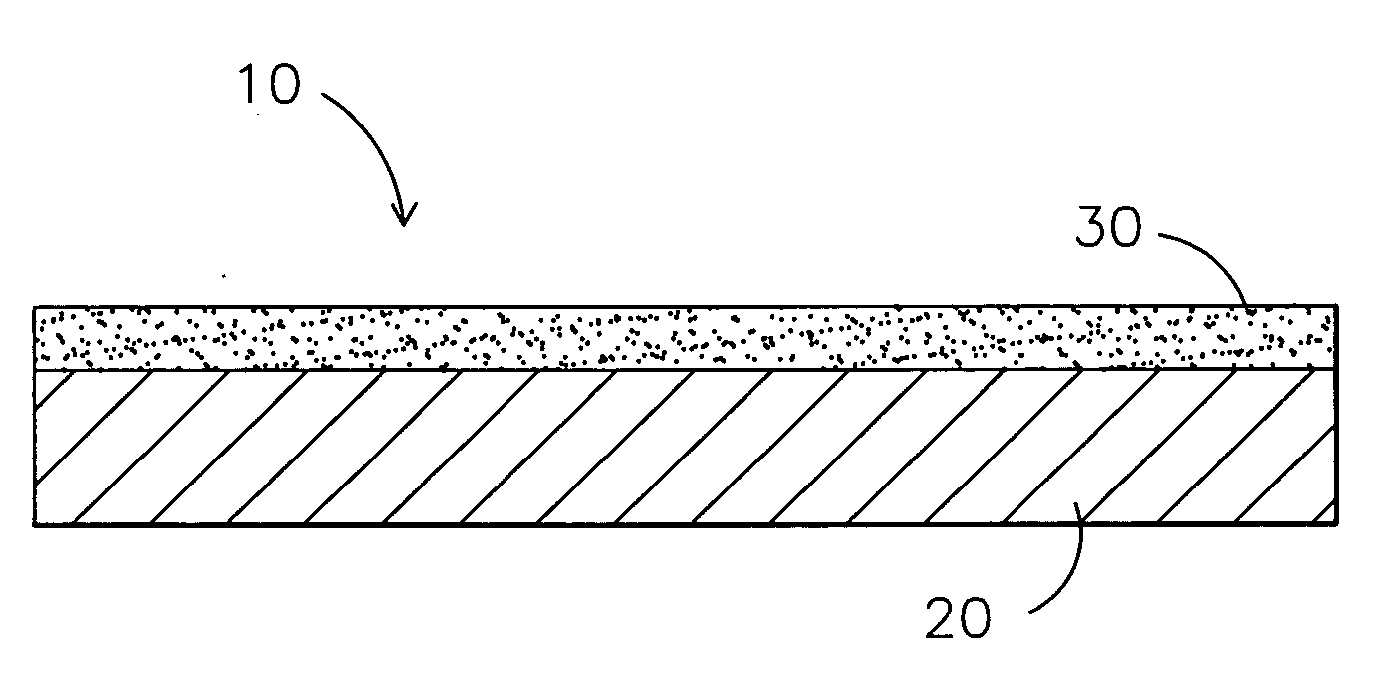
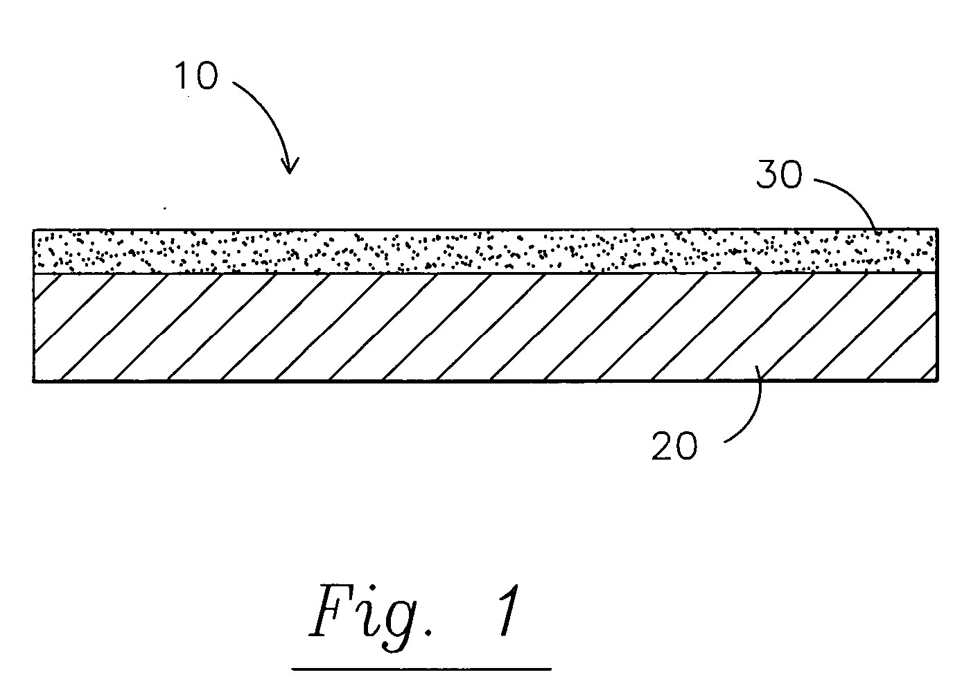
Image

Examples
example 1
[0099] Step 1. 35 grams of 30 / 60 coal slag was provided. The coal slag contained 25% Aluminum Oxide, 25% Iron Oxide, and 50% Mineralized Glass.
[0100] Step 2. The coal slag was coated with 15 grams of a six micron (6μ) silver powder. The silver powder was slightly moistened and adhered to the coal slag.
[0101] Step 3. Then, 25 grams of white silica powder—250 sieve screen was added to the top of the silver powder. The silica powder adhered to the silver powder.
[0102] Step 4. Finally, 25 grams of a mixture of pharmacy grade calcium, magnesium, and zinc powder. The 25% of the mixture contains 60% weight of calcium, 28% weight of magnesium, and 12% weight of zinc.
[0103] The three elements of step 4 are pharmacy grade and were purchased over the counter at a local drug store in tablet form and then finely ground.
[0104] Results of the test for example 1:
[0105] A test was done using a 2½ ounce round spherical container ¾″ diameter×1½″ long of iron filings, a 28 lb pull ¾″ diameter×½″ ...
example 2
[0116] Step 1. 33 grams of 30 / 60 coal slag was provided. The coal slag contained 25% Aluminum Oxide, 25% Iron Oxide, and 50% Mineralized Glass.
[0117] Step 2. The coal slag was coated with 15 grams of a six micron (6μ) silver powder. The silver powder was slightly moistened and adhered to the coal slag.
[0118] Step 3. Then, 25 grams of white silica powder—250 sieve screen was added to the top of the silver powder. The silica powder adhered to the silver powder.
[0119] Step 4. Finally, 20 grams of a mixture of pharmacy grade calcium, magnesium, and zinc powder. The 25% of the mixture contains 60% weight of calcium, 28% weight of magnesium, and 12% weight of zinc. The 20% of the mixture contains 60% weight of calcium, 28% weight of magnesium, and 12% weight of zinc.
[0120] The three elements of step 4 are pharmacy grade and were purchased over the counter at a local drug store in tablet form and then finely ground.
[0121] Step 5. 7 grams of nano-silver were mixed with the mixture of s...
example 3
[0136] The objective of the experiment was to create a static distortion on a radio.
[0137] An AM radio and another electronic device were set approximately 12 inches apart.
[0138] An adhesive was sprayed on a plain sheet of paper, and the shielding material of example 1 was applied to the paper.
[0139] The paper was then lowered between the two devices.
[0140] The result was a very noticeable reduction in the static on the radio.
[0141] The magnetic shield, according to the present invention, is of much lighter weight than the ferrous shields of the prior art.
[0142] The magnetic shield of the present invention may be used with: [0143] MRI units for shielding of errant and stray fields; [0144] power transfer for AC power line transformers; [0145] security installations, conference rooms, command centers, and test facilities; [0146] electronic equipments such as computers and other sensitive systems; and [0147] auto industry for everything from propulsion to electronic protection.
[...
PUM
| Property | Measurement | Unit |
|---|---|---|
| Percent by mass | aaaaa | aaaaa |
| Percent by mass | aaaaa | aaaaa |
| Percent by mass | aaaaa | aaaaa |
Abstract
Description
Claims
Application Information
 - R&D
- Intellectual Property
- Life Sciences
- Materials
- Tech Scout
- Unparalleled Data Quality
- Higher Quality Content
- 60% Fewer Hallucinations
Browse by: Latest US Patents, China's latest patents, Technical Efficacy Thesaurus, Application Domain, Technology Topic, Popular Technical Reports.
© 2025 PatSnap. All rights reserved.Legal|Privacy policy|Modern Slavery Act Transparency Statement|Sitemap|About US| Contact US: help@patsnap.com