System and method for controlling a light source for cavity ring-down spectroscopy

a technology of ring-down spectroscopy and control system, which is applied in the field of absorption spectroscopy, can solve the problems of primarily light energy loss, difficult use and impracticality for industrial applications, and reduce the yield of operational circuits

Inactive Publication Date: 2006-04-27
TIGER OPTICS L L C
View PDF16 Cites 12 Cited by
  • Summary
  • Abstract
  • Description
  • Claims
  • Application Information

AI Technical Summary

Benefits of technology

[0014] To achieve that and other objects, and in view of its purposes, the present invention provides an improved apparatus and method for controlling a light source for use with a resonant cavity. The apparatus includes a controller for receiving a comparison of a detection signal and a predetermined threshold, the comparator generating a control signal to one of acti

Problems solved by technology

Gases such as N2, O2, H2, Ar, and He are used to manufacture integrated circuits, for example, and the presence in those gases of impurities—even at parts per billion (ppb) levels—is damaging and reduces the yield of operational circuits.
Further, the presence of impurities, either inherent or deliberately placed, in liquids have become of particular concern of late.
These methods have several features, discussed

Method used


Image

  • System and method for controlling a light source for cavity ring-down spectroscopy
  • System and method for controlling a light source for cavity ring-down spectroscopy
  • System and method for controlling a light source for cavity ring-down spectroscopy

Examples


Embodiment Construction

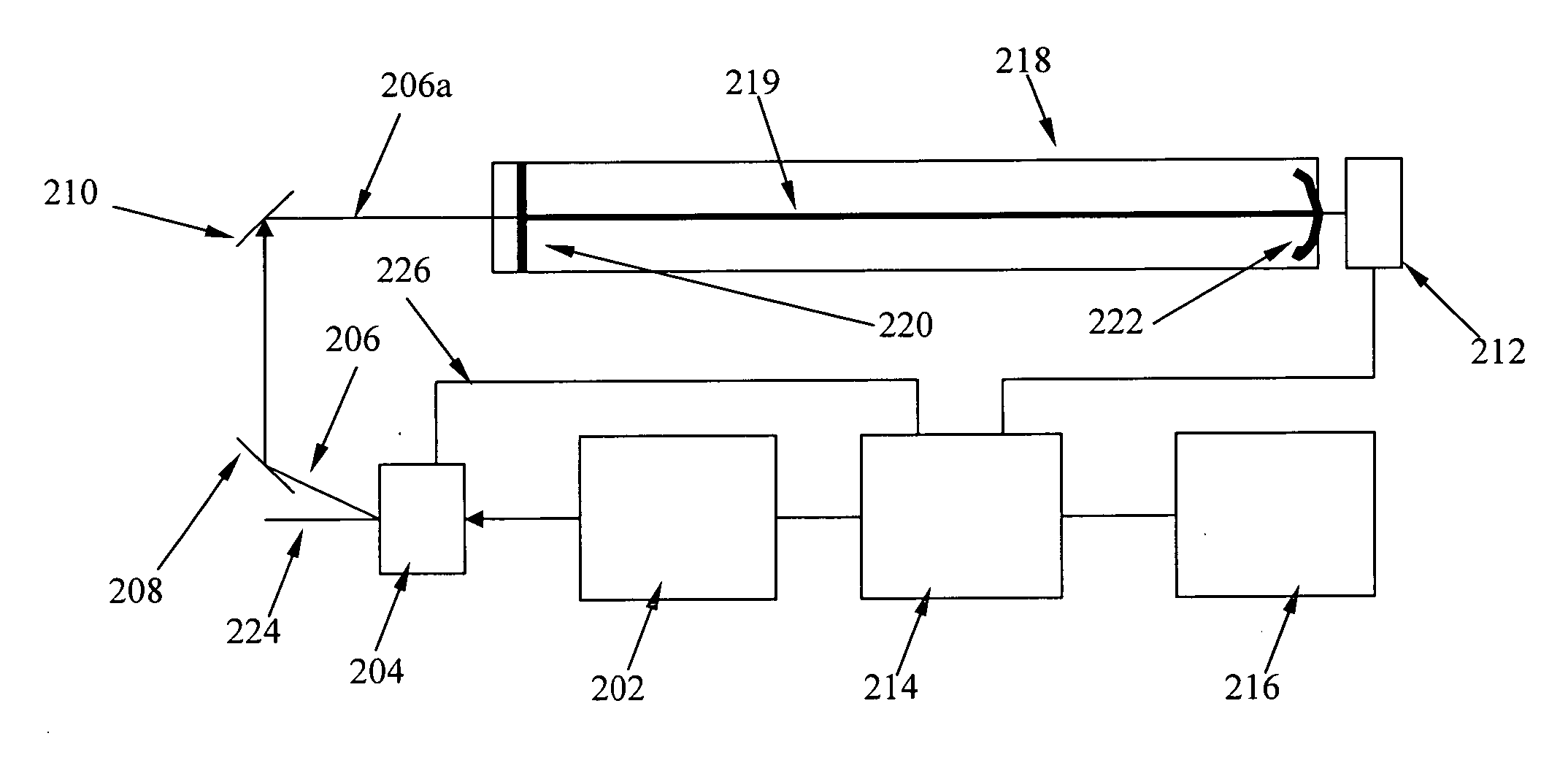
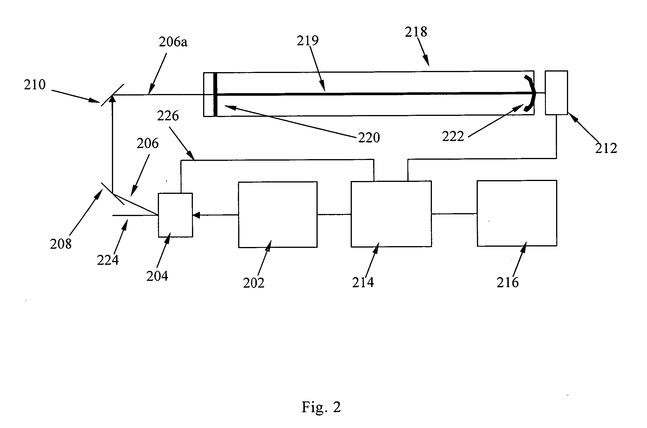
[0040]FIG. 3A illustrates an exemplary embodiment of the present invention. As shown in FIG. 3A, light is generated from light source 302, such as a narrow band, tunable, continuous wave diode laser. Light source 302 is temperature tuned by a temperature controller (not shown) to put its wavelength on the desired spectral line of the analyte of interest. Light energy from light source 302 is coupled to fiber collimator 308 through optical fiber 304. Light energy 306 is, in turn, provided by collimator 308 to resonant cavity 318 and substantially parallel to its optical axis 319. Detector 312 is coupled to the output of optical cavity 318. In turn, detector 312 generates an output signal 313 and provides this signal to controller 314 and data analysis system 316. Controller 314 is coupled to light source 302 and data analysis system 316. Data analysis system 316, such as a personal computer or other specialized processor, processes signals 313 received from optical detector 312, in a...


PUM


Abstract

An apparatus and method for controlling a light source used in Cavity Ring-Down Spectroscopy. The apparatus comprises a controller that generates a control signal to activate and deactivate the light source based on a comparison of an energy signal from a resonant cavity and a threshold. The light source is activated for a time period based on the stabilization time of the light source and the time necessary to provide sufficient energy to the resonant cavity. Thereafter the controller deactivates the light source for a predetermined time period by interrupting its current source so that the light energy in the cavity rings down and so that the presence of analyte can be measured. The light energy from the light source is directly coupled to the resonant cavity from the light source.

Description

[0001] This application is a Continuation-in-Part of application Ser. No. 10 / 145,209 filed on May 13, 2002.FIELD OF THE INVENTION [0002] This invention relates generally to absorption spectroscopy and, in particular, is directed to the activation and deactivation of a light source for use with an optical resonator for cavity ring-down spectroscopy. BACKGROUND OF THE INVENTION [0003] Referring now to the drawing, wherein like reference numerals refer to like elements throughout, FIG. 1 illustrates the electromagnetic spectrum on a logarithmic scale. The science of spectroscopy studies spectra. In contrast with sciences concerned with other parts of the spectrum, optics particularly involves visible and near-visible light—a very narrow part of the available spectrum which extends in wavelength from about 1 mm to about 1 nm. Near visible light includes colors redder than red (infrared) and colors more violet than violet (ultraviolet). The range extends just far enough to either side of...

Claims


Application Information

Patent Timeline
IPC IPC(8): G01N21/61G01N21/01G01J3/10G01N21/39
CPCG01N21/39G01J3/10
Inventor AUGUSTINE, ROBERTKRUSEN, CALVIN R.WANG, CHUJIYAN, WEN-BIN
Owner TIGER OPTICS L L C
Why Eureka
Try Eureka