Magnetic recording head for perpendicular recording, fabrication process, and magnetic disk storage apparatus mounting the magnetic recording head
- Summary
- Abstract
- Description
- Claims
- Application Information
AI Technical Summary
Benefits of technology
Problems solved by technology
Method used
Image

Examples
embodiment 1
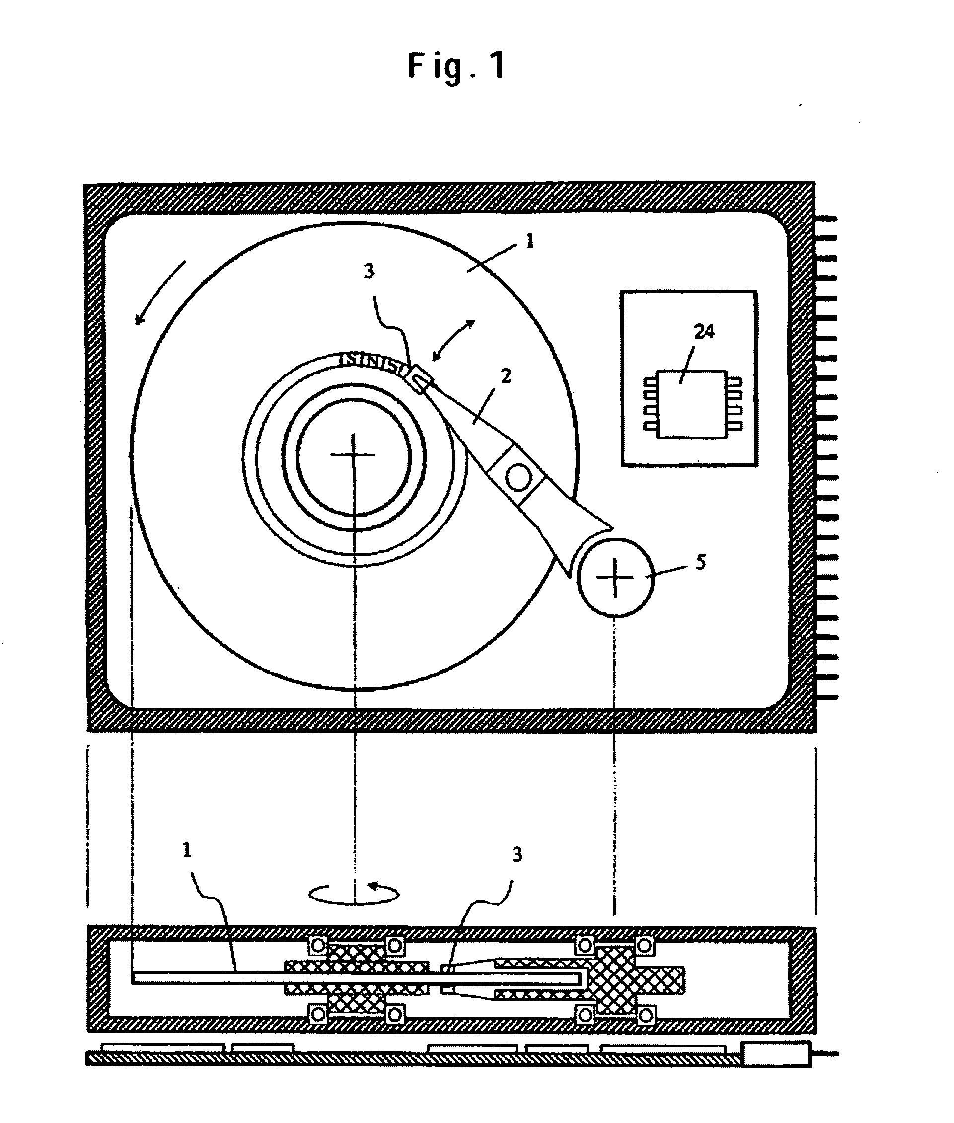
[0027]FIG. 1 schematically depicts a magnetic recording and reproducing device. The upper diagram provides its top view whereas the lower diagram provides its sectional view. In the magnetic recording and reproducing device, a magnetization signal is written and read on a motor-driven rotating magnetic disk by a magnetic head 3 fixed on the tip of an arm 2 above the magnetic disk 1. The arm 2 is driven in the disk's radial direction by an actuator 5 to locate a track for read or write. The magnetic slider 3 is held by the arm via gimbals. The write signal to energize the magnetic head in the slider 3 or the read signal sent out from the magnetic head is processed by a signal processing circuit 24.
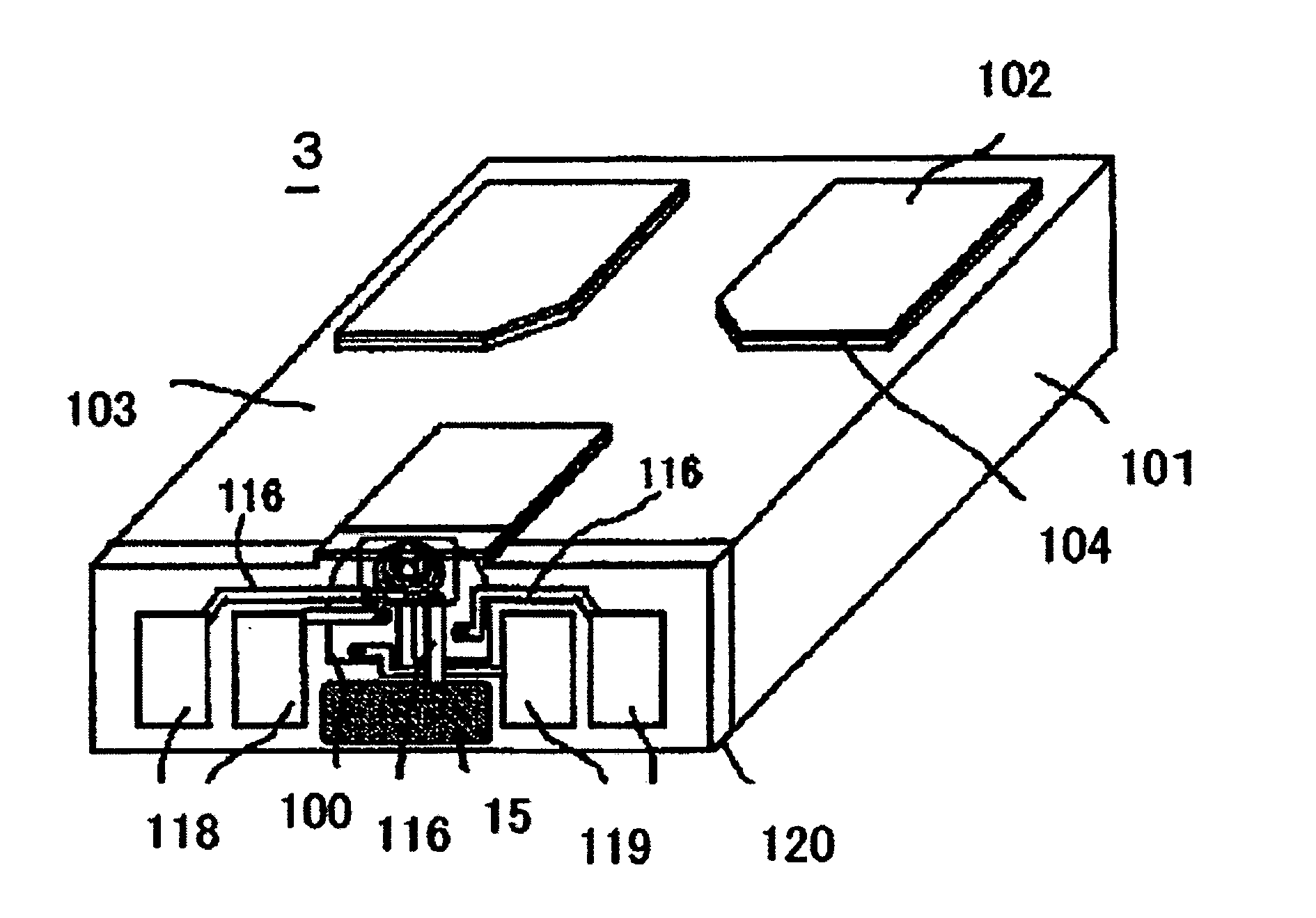
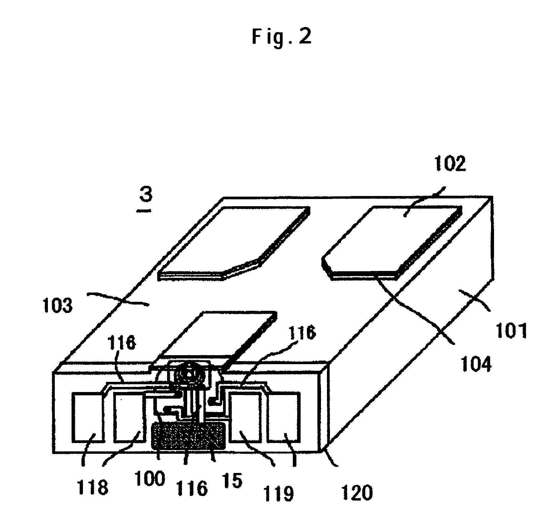
[0028]FIG. 2 schematically depicts the configuration of the magnetic slider 3. Reference numeral 101 refers to a substrate. Reference numeral 100 is a magnetic read-write element constructed of a combination of a magnetic read element and a magnetic write element which are formed on the su...
embodiment 2
[0033]FIG. 10 is a sectional view of a magnetic slider 3 according to a second embodiment or a modified example of the first embodiment while FIG. 11 is a plan view showing the shapes of the coil and the magnetic pole which are depicted on the basis of superimposition. The portion I of the section in FIG. 10 corresponds to line A-A′ shown in FIG. 11. This example is different from the first embodiment in that a wire 20 is formed by coating the nonmagnetic wire 17 with a magnetic material. When the nonmagnetic wire 17 is made of such a material as copper, if such a process as ion milling is performed to selectively etch a grown copper film, copper seeds may deposit again on the copper film. If copper seeds are detached, it is possible that wires may be short-circuited. Thus, the upper and side surfaces of the nonmagnetic wire 17 are partly coated with a magnetic film of NiFe or the like having relatively high corrosion resistance. This makes it possible to selectively remove the grow...
embodiment 3
[0034]FIG. 12 is a sectional view of a magnetic slider 3 according to a third embodiment or a modified example of the first and second embodiments while FIG. 11 is a plan view showing the shapes of the coil and the magnetic pole which are depicted on the basis of superimposition. The portion I of the section in FIG. 12 corresponds to line A-A′ shown in FIG. 13. This embodiment is different from the first embodiment in that a wire 20 is formed by partly coating the nonmagnetic wire 17 with a magnetic material. What is different from the second embodiment is that a magnetic film 20a is formed on the top of the main magnetic pole piece 12 in addition to that formed below the plug of the anti-corrosion terminal 15. Since the magnetic film is bonded to the main magnetic pole piece via the magnetic film, that is, the main magnetic pole piece is not in direct contact with nonmagnetic material, it is possible to prevent the main magnetic pole piece from corroding during wet etching of the g...
PUM
 Abstract
Description
Claims
Application Information
 - Generate Ideas
- Intellectual Property
- Life Sciences
- Materials
- Tech Scout
- Unparalleled Data Quality
- Higher Quality Content
- 60% Fewer Hallucinations
Browse by: Latest US Patents, China's latest patents, Technical Efficacy Thesaurus, Application Domain, Technology Topic, Popular Technical Reports.
© 2025 PatSnap. All rights reserved.Legal|Privacy policy|Modern Slavery Act Transparency Statement|Sitemap|About US| Contact US: help@patsnap.com