Multi-wavelength optical transceiver subassembly module

a technology of optical transceivers and sub-assemblies, applied in the field of multi-wavelength optical transceivers, can solve the problems of increasing manufacturing costs, power consumption, and affecting the coupling efficiency of the system, and achieve the effect of enhancing coupling efficiency

Inactive Publication Date: 2006-04-27
NAT TAIWAN UNIV
View PDF4 Cites 77 Cited by
  • Summary
  • Abstract
  • Description
  • Claims
  • Application Information

AI Technical Summary

Benefits of technology

[0014] The primary objective of the present invention is to provide an optical transceiver subassembly module with flexible structure that enables the active alignment of a laser diode or a photo detector relative to an optical transmitter or an optical receiver, thereby enhancing the coupling efficiency between optical signals and an optical fiber.
[0015] Another objective of the present invention is to provide an optical transceiver subassembly module that allows for passive alignment for enhancing coupling efficiency between optical signals and optical fibers.
[0016] A further object of the present invention is to provide an optical transceiver subassembly having a compact construction by arranging a number of laser diodes or photo detectors in such a way that a star-shaped optical path is formed among the laser diodes or photo detectors, which allows for reduction of overall size to meet the trend of miniaturization.

Problems solved by technology

Conventionally, high speed transmissions up to 10 Gb / sec, 40 Gb / sec, or even higher, is realized by increasing the operation frequency of the transmitter driver circuit, which inevitably leads to a significant increase of manufacturing costs.
All these add to the manufacturing costs, as well as power consumption.
Also, using laser diodes with lower transmission speeds makes the design for the electrical subassembly (ESA) and driver circuit less critical, but the more challenging part is the design of the optical subassembly (OSA), which is to combine optical signals of different wavelengths and couple them onto a single optical fiber (the part of TOSA), or to separate multiplexed optical signals on the receiver end of the optical fiber into optical wavelength signals to respective photo detectors (the part of ROSA), and at the same time the design spec has to meet the Multi Source Agreement (MSA) and the module miniaturization.
Thus, for precise alignment, the fastening means must be of high manufacturing precision and this inevitably complicates the manufacturing process and increases the manufacturing costs.

Method used


Image

  • Multi-wavelength optical transceiver subassembly module
  • Multi-wavelength optical transceiver subassembly module
  • Multi-wavelength optical transceiver subassembly module

Examples


Embodiment Construction

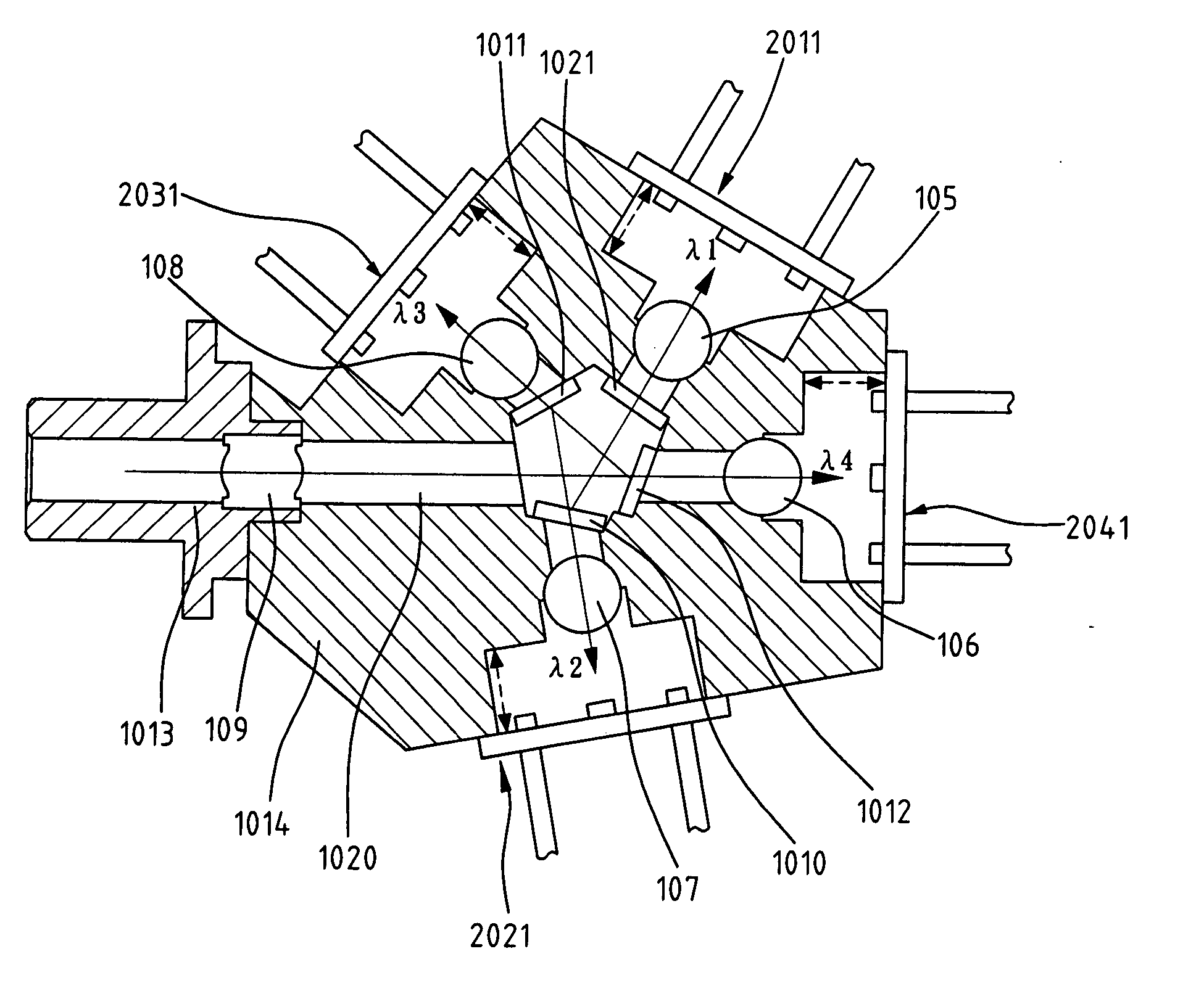
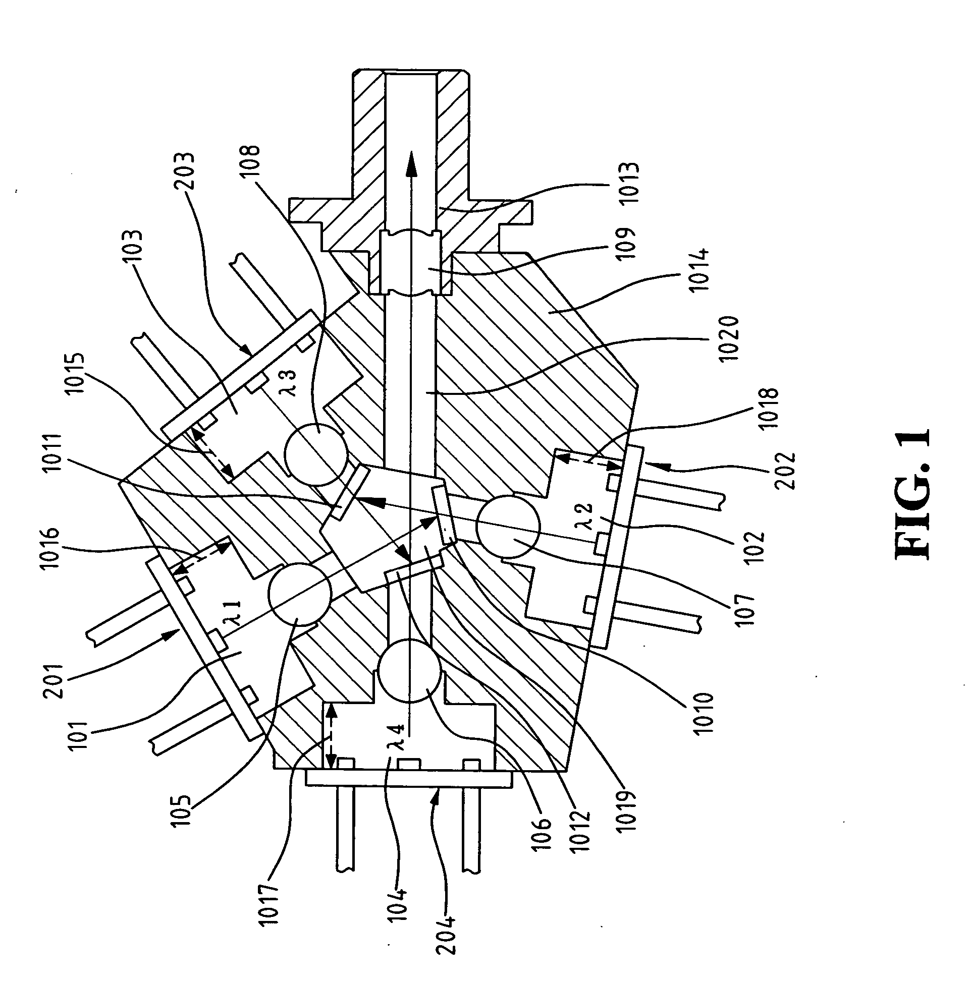
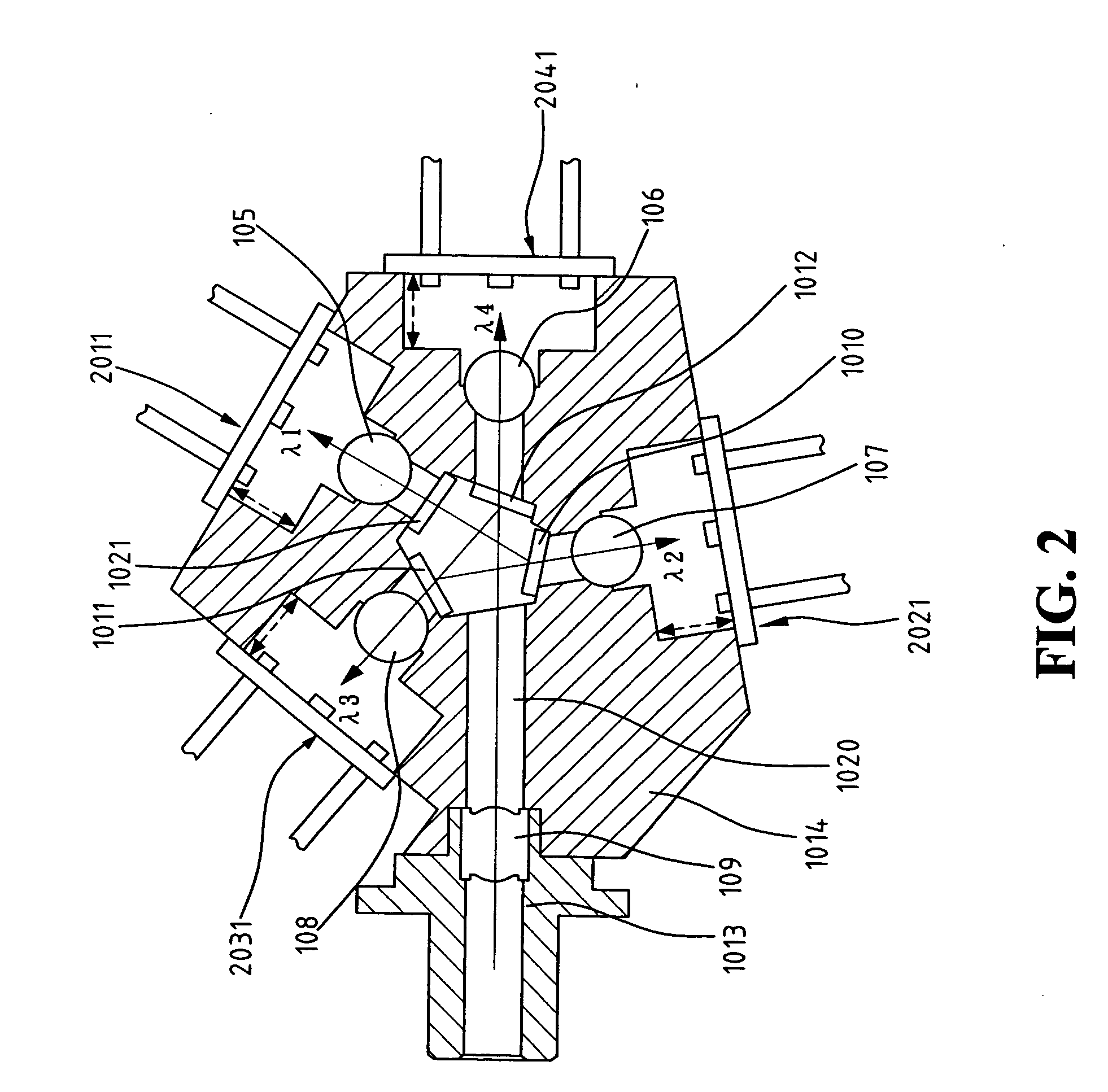
[0037] With reference to the drawings and in particular to FIG. 1, an optical transmitter constructed in accordance with the present invention comprises a main body 1014 in which first, second, third and fourth alignment slot 101, 102, 103, 104 are defined. Also defined in the transmitter main body 1014 is a central cavity 1019 that is in communication with each alignment slot 101-104 via a passageway (not shown) that has an axis. The alignment slots 101-104 are of predetermined depths 1016, 1018, 1015, and 1017 to match laser beams of different wavelengths. Each alignment slot 101-104 receives a laser diode device 201, 202, 203, and 204 that a laser beam carrying an optical signal transmits along the associated passageway toward the central cavity 1019. A lens 105, 107, 108, 106, such as a spherical lens, an aspheric lens, and a set of lenses, is retained in each passageway to collimate the laser beam. If desired, surfaces of the lens 105-108 are coated with anti-reflective layers ...


PUM


Abstract

Disclosed is an optical transceiver subassembly module for multiplexing and demultiplexing a plurality of channels of different wavelengths. The optical subassembly module includes a transmitter optical subassembly (TOSA) and a receiver optical subassembly (ROSA). For a TOSA, the optical signals emitted by four laser diodes of different wavelengths are combined into a multiplexed optical signal, through respective thin film filters and lenses, which is then coupled onto an optical fiber after passing through a focusing lens. For a ROSA, the input optical signal on the receiver end of the optical fiber is separated into multiple optical wavelength signals, through respective thin film filters and lenses, which are then registered by respective photo detectors. This optical subassembly module with compact star-shaped optics design, active and passive alignments is able to attain high coupling efficiency between optical signals and the optical fiber.

Description

BACKGROUND OF THE INVENTION [0001] 1. Field of the Invention [0002] The present invention relates to a multi-wavelength optical transceiver subassembly module that is applicable to long-haul, metropolitan area network (MAN), and local area network (LAN) signal transmission in telecommunications and data communications. [0003] 2. The Related Arts [0004] Optical fiber transmission is instrumental in the development of many advanced applications for telecommunications and data communications. This high bandwidth transmission needs local fiber access to provide two-way communications to the home through an optical transceiver, which is composed of a driver circuit, an electrical subassembly (ESA), and an optical subassembly (OSA). Operation frequency plays a critical role in determining the transmission speed. Conventionally, high speed transmissions up to 10 Gb / sec, 40 Gb / sec, or even higher, is realized by increasing the operation frequency of the transmitter driver circuit, which ine...

Claims


Application Information

Patent Timeline
Patent Type & Authority Applications(United States)
IPC IPC(8): G02B6/42
CPCG02B6/29361G02B6/2938G02B6/4204G02B6/4215
Inventor WU, ENBOASHIH, YING-CHING
Owner NAT TAIWAN UNIV
Why Eureka
Try Eureka