Organic light emitting diode

a light-emitting diode and organic technology, applied in the direction of organic semiconductor devices, discharge tube luminescnet screens, superimposed coating processes, etc., can solve the problems of reducing the work function of the anode, reducing the luminous efficiency, and not being able to achieve colorization or high accuracy. the effect of high efficiency, enhanced productivity of the pixel electrode, and improved reflectan

Active Publication Date: 2006-05-04
SAMSUNG DISPLAY CO LTD
View PDF6 Cites 44 Cited by
  • Summary
  • Abstract
  • Description
  • Claims
  • Application Information

AI Technical Summary

Benefits of technology

[0013] The present invention solves aforementioned problems by providing an organic light emitting diode comprising a pixel electrode having a multi-layered structure (i.e. a multilayer pixel e

Problems solved by technology

However, the single layer anode has a decreased work function as time progresses, which causes luminous efficiency to be decreased, so that it is not easy to implement colorization or high accuracy which the consumer desires to have.
However, in the process of forming the anode using the silver or silver alloy, an electr

Method used


Image

  • Organic light emitting diode
  • Organic light emitting diode
  • Organic light emitting diode

Examples


Embodiment Construction

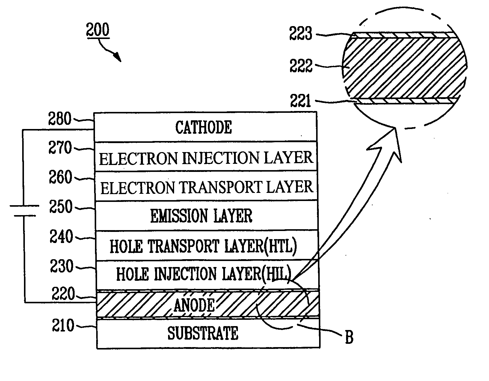
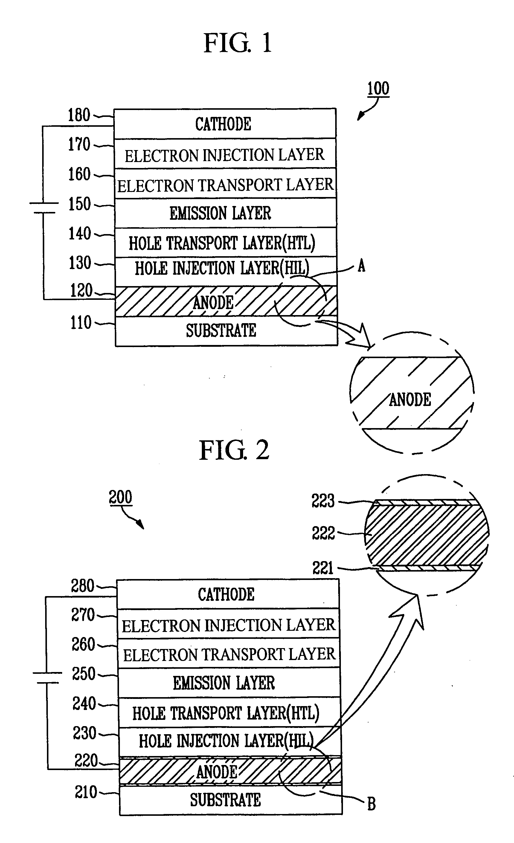
[0022]FIG. 1 is a side cross-sectional view schematically illustrating an organic light emitting diode including a conventional pixel electrode. Referring to FIG. 1, the organic light emitting diode 100 includes a substrate 110, a pixel electrode 120 (hereinafter, referred to as an “anode”) formed on the substrate 110, an emission layer 150 formed on the anode 120, and a counter electrode 180 (hereinafter referred to as a “cathode”). In addition, the organic light emitting diode 100 includes a hole injection layer (HIL) 130 and a hole transport layer (HTL) 140 formed on the anode 120, and an electron transport layer (ETL) 160 and an electron injection layer (EIL) 170 formed on the emission layer 150. In this case, the anode 120 has a high work function, and is an electrode composed of a single layer formed of transparent and conductive metal oxide such as Indium Tin oxide (ITO) and Indium Zinc Oxide (IZO) (see the A region of FIG. 1).

[0023] When a voltage is applied between the ano...


PUM

PropertyMeasurementUnit
Timeaaaaaaaaaa
Thicknessaaaaaaaaaa

Abstract

An organic light emitting diode, which has a pixel electrode, the pixel electrode constructed with a first layer comprising metal oxide on the substrate; a second layer comprising silver alloyed with at least one metal selected from a group consisting of lanthanide series elements and actinide series elements on the first layer; and a third layer comprising metal oxide on the second layer. As such, there are provided the second layer comprising the silver alloy, and the first and third layer comprising the metal oxide and formed above and below the second layer so that adhesion of a silver alloy (e.g., ATD alloy) may be enhanced, and an anode having enhanced reflectance may also be provided by using silver with increased reflectance.

Description

CLAIM OF PRIORITY [0001] This application claims priority to and the benefit of Korean Patent Application No. 2004-86913, filed Oct. 28, 2004, the disclosure of which is hereby incorporated herein by reference in its entirety. BACKGROUND [0002] 1. Field of the Invention [0003] The present invention relates to an organic light emitting diode including a pixel electrode formed on a substrate, and more particularly, to an organic light emitting diode improved in adhesion with the substrate and reflectance. [0004] 2. Discussion of Related Art [0005] An organic light emitting diode is a diode which generates light using an organic material which emits lights when current flows through electrodes, and typically includes a pair of electrodes composed of a pixel electrode and a counter electrode, and an emission layer. The organic light emitting diode optionally further includes, between the pixel and counter electrodes a hole injection layer (HIL), a hole transport layer (HTL), an electron...

Claims


Application Information

Patent Timeline
IPC IPC(8): H05B33/00H01J1/62
CPCC22C5/06H01L51/5206H01L2251/5315H05B33/26C23C28/321C23C28/345H10K50/818H10K2102/3026
Inventor SHIN, HYUN-EOK
Owner SAMSUNG DISPLAY CO LTD
Why Eureka
Try Eureka