System and method for supplying precursor gases to an implantation tool

a technology of precursor gas and ion implantation, which is applied in the direction of ion implantation coating, chemical vapor deposition coating, coating, etc., can solve the problems of insufficient gas release rate from adsorbent material, unstable plasma in the ion source, and difficulty in extracting all of the precursor gas from the bottle, etc., to increase the risk of environmental contamination, increase the gas flow stability, and use more efficiently

Inactive Publication Date: 2006-05-04
GLOBALFOUNDRIES INC
View PDF17 Cites 18 Cited by
  • Summary
  • Abstract
  • Description
  • Claims
  • Application Information

AI Technical Summary

Benefits of technology

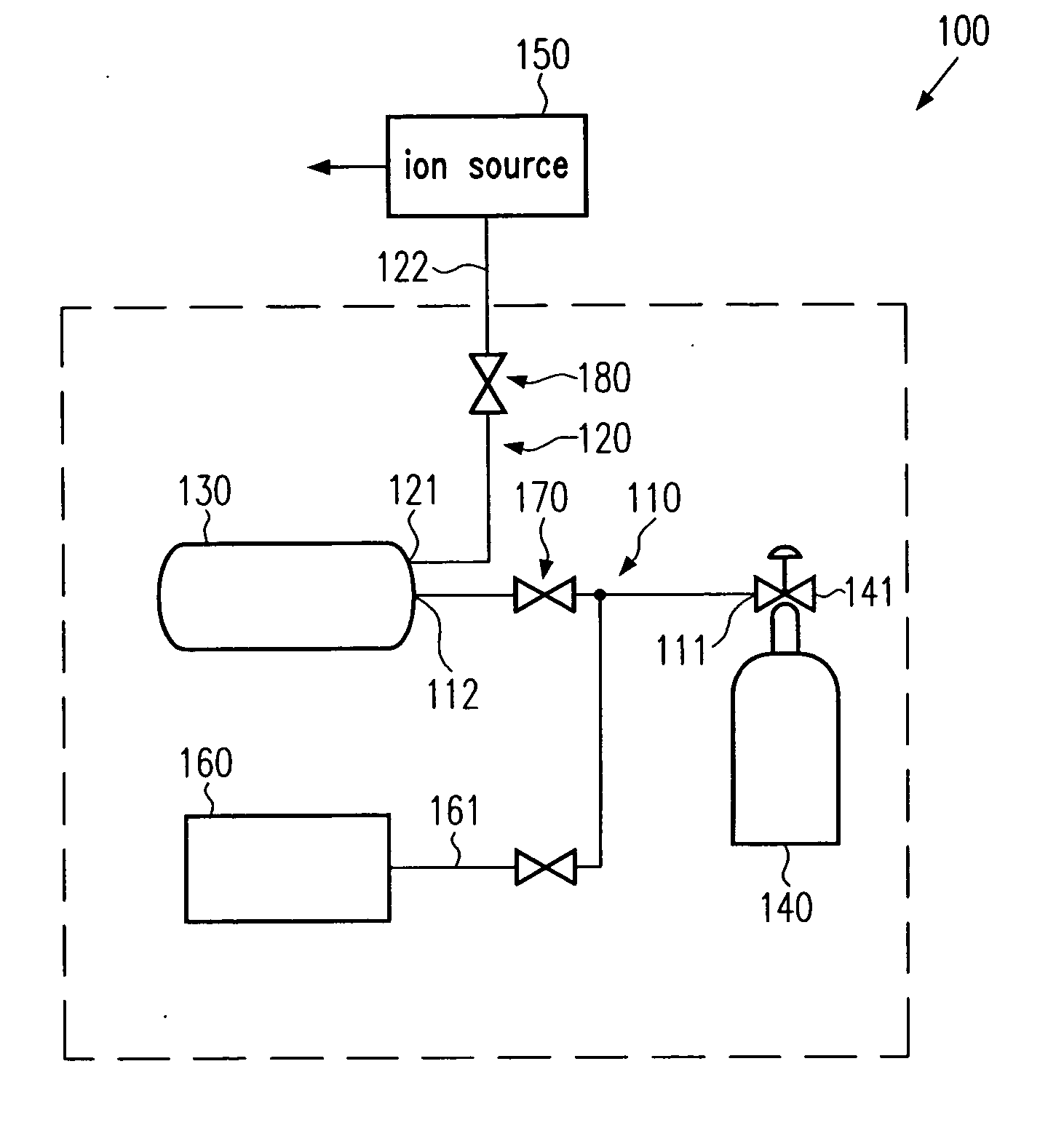
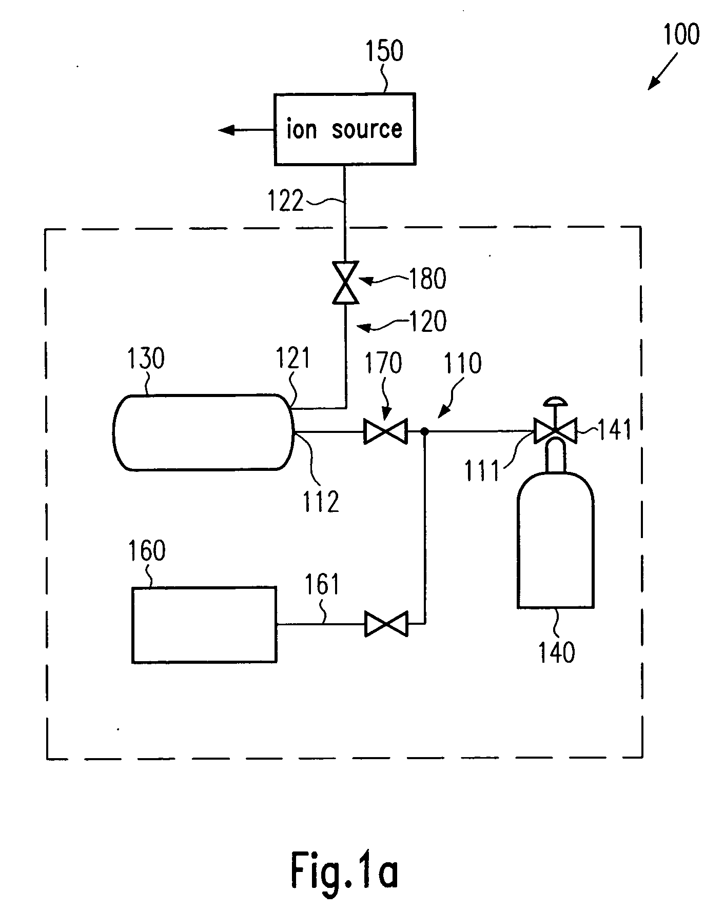
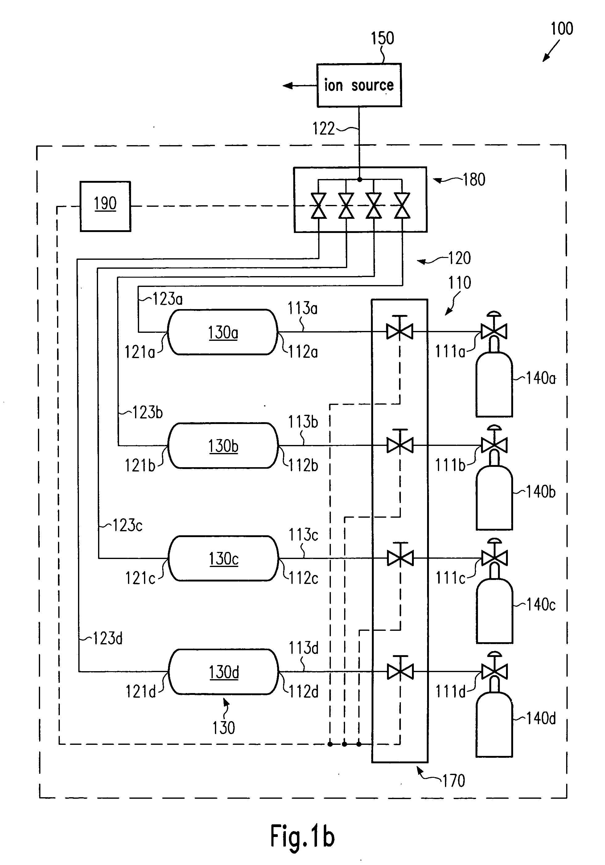
[0011] Generally, the present invention is directed to a technique that enables the utilization of a significantly increased amount of precursor gas stored in an SDS gas bottle at a high tool utilization while not unduly increasing the risk of environmental contaminations, which may conventionally be caused by an increased number of gas bottle changes. According to embodiments of the present invention, the initial contents of an SDS gas bottle may be used more efficiently in that an additional gas buffer volume is provided between the SDS gas bottle and the ion source of an implantation tool, thereby significantly increasing the gas flow stability and the amount of gas extracted from the adsorbent material within the SDS gas bottle.

Problems solved by technology

Many of these precursor gases, such as BF3, AsH3, PH3, etc., are extremely hazardous, and thus require specific measures in handling the gas bottles and the supply system to substantially avoid any environmental contamination with these gases.
During operation of the gas supply system, it turns out, however, that it is extremely difficult to extract all of the precursor gas from the bottle owing to the restricted gas release rate of the adsorbent material, and thus the adsorbent material remains partially filled with the precursor gas.
A further problem arises when the gas bottle is increasingly exhausted, since then the decreasing gas release rate from the adsorbent material may not be sufficient to maintain a stable gas flow for extended time periods.
As a consequence of the reduced gas flow stability, the plasma in the ion source may become unstable or may vary and the corresponding plasma fluctuations may significantly affect the operation of the entire ion implantation tool.
As previously pointed out, especially advanced semiconductor devices require highly sophisticated implantation profiles so that process variations caused by gas flow instabilities may not be acceptable and may require a premature change of the respective gas bottles.
It turns out, however, that the adsorbent material may hold back up to nearly 10% of the precursor gas initially filled into the bottle, thereby rendering SDS gas bottles as moderately inefficient in view of cost of ownership.
Although this process technique may allow increased utilization of the precursor gas in an SDS gas bottle, the problem of unstable gas flow is only postponed and may now require a premature gas bottle change at the medium current implantation tool.
Moreover, an additional change of a gas bottle with extremely hazardous gases is required, thereby not only increasing the risk for environmental contamination, but also increasing the down time of the ion implantation tools.

Method used


Image

  • System and method for supplying precursor gases to an implantation tool
  • System and method for supplying precursor gases to an implantation tool
  • System and method for supplying precursor gases to an implantation tool

Examples


Embodiment Construction

[0019] Illustrative embodiments of the invention are described below. In the interest of clarity, not all features of an actual implementation are described in this specification. It will of course be appreciated that in the development of any such actual embodiment, numerous implementation-specific decisions must be made to achieve the developers' specific goals, such as compliance with system-related and business-related constraints, which will vary from one implementation to another. Moreover, it will be appreciated that such a development effort might be complex and time-consuming, but would nevertheless be a routine undertaking for those of ordinary skill in the art having the benefit of this disclosure.

[0020] The present invention will now be described with reference to the attached figures. Various structures, systems and devices are schematically depicted in the drawings for purposes of explanation only and so as to not obscure the present invention with details that are we...


PUM

PropertyMeasurementUnit
acceleration voltageaaaaaaaaaa

Abstract

An improved supply system for an ion source of an ion implantation tool and a method of operating the same is provided. By using a buffer volume between an SDS gas bottle and the ion source, stability of the gas flow to the ion source is significantly enhanced, while at the same time nearly all of the gas contents in the gas bottle may be available during operation of the ion implantation tool.

Description

BACKGROUND OF THE INVENTION [0001] 1. Field of the Invention [0002] The present invention generally relates to the fabrication of microstructures, such as integrated circuits, and, more particularly, to ion implantation tools and peripheral components thereof which are required to produce well-defined dopant profiles in device regions. [0003] 2. Description of the Related Art [0004] The fabrication of complex microstructures, such as sophisticated integrated circuits, requires that a large number of individual process steps be performed to finally obtain the required functionality of the microstructure. Especially in the formation of integrated circuits, the conductivity of specific areas has to be adapted to design requirements. For instance, the conductivity of a semiconductor region may be increased in a well-defined manner by introducing specific impurities, which are also referred to as dopants, and placing some or preferably all of these impurities at lattice sites of the semi...

Claims


Application Information

Patent Timeline
Patent Type & Authority Applications(United States)
IPC IPC(8): C23C14/00H01J7/24C23C16/00H05B31/26
CPCC23C14/48H01J37/08H01J37/3171
Inventor KRUEGER, CHRISTIANKOCIS, RASTISLAV
Owner GLOBALFOUNDRIES INC
Why Eureka
Try Eureka