Synthetic turf

a synthetic turf and rubber technology, applied in the field of synthetic turf, can solve the problems of limited life span, insufficient resilience or shock absorption of synthetic turf use, and inability to be reused, and achieve the effect of reducing the coefficient of friction, reducing the number of burns, and reducing the resilience of polyethylene yarns

Inactive Publication Date: 2006-05-04
DOMO ZELE
View PDF14 Cites 57 Cited by
  • Summary
  • Abstract
  • Description
  • Claims
  • Application Information

AI Technical Summary

Benefits of technology

[0016] An important advantage of these embodiments is that the synthetic turf can be rendered more sliding-friendly, i.e. its coefficient of friction can be made smaller than for example the coefficient of friction of polypropylene so that burning wounds arise less quickly. Due to the fact that the individual filament yarns are twined together with a fibrillated yarn in the composite yarn, the smaller resilience properties of the polyethylene yarns compared to for example polypropylene yarns, are partially comp

Problems solved by technology

However, these rubbers have several important disadvantages.
In particular, they can not be re-used and have a limited life span since they loose there properties throughout use.
Furthermore, the use of this type of rubbers in a top-dressing layer of a synthetic turf does not provide sufficient resilience or shock absorption.
A drawback of the used fibrillated yarns is that they have a relatively low wear resistance and that a post-fibrillation with a rigid (steel) brush is required after having laid the synthetic turf.
A drawback of such a post-fibrillation is however that the pile yarn is damaged.
A drawback of synthetic turf made of monotape or monofilaments is that the top-dressing is less stabilised against shifting and/or erosion and tha

Method used


Image

  • Synthetic turf
  • Synthetic turf

Examples


example 1

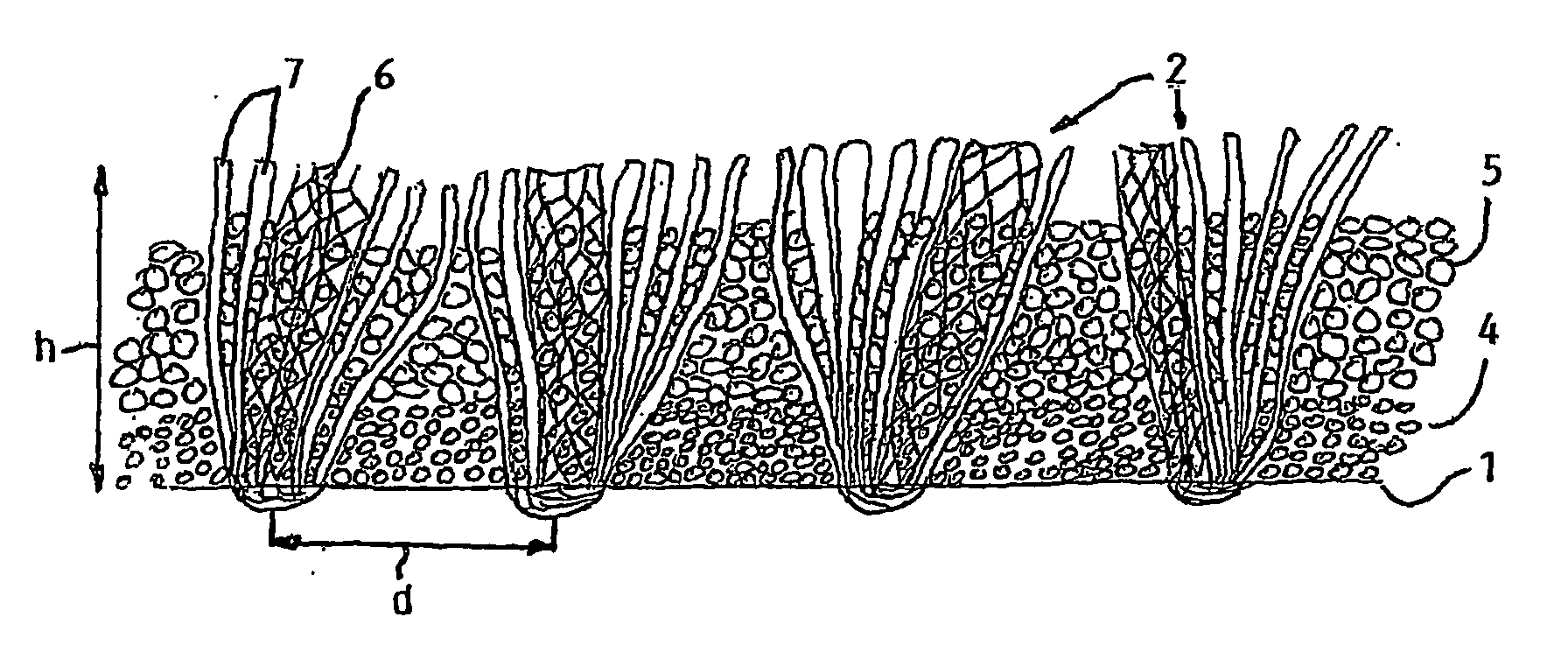
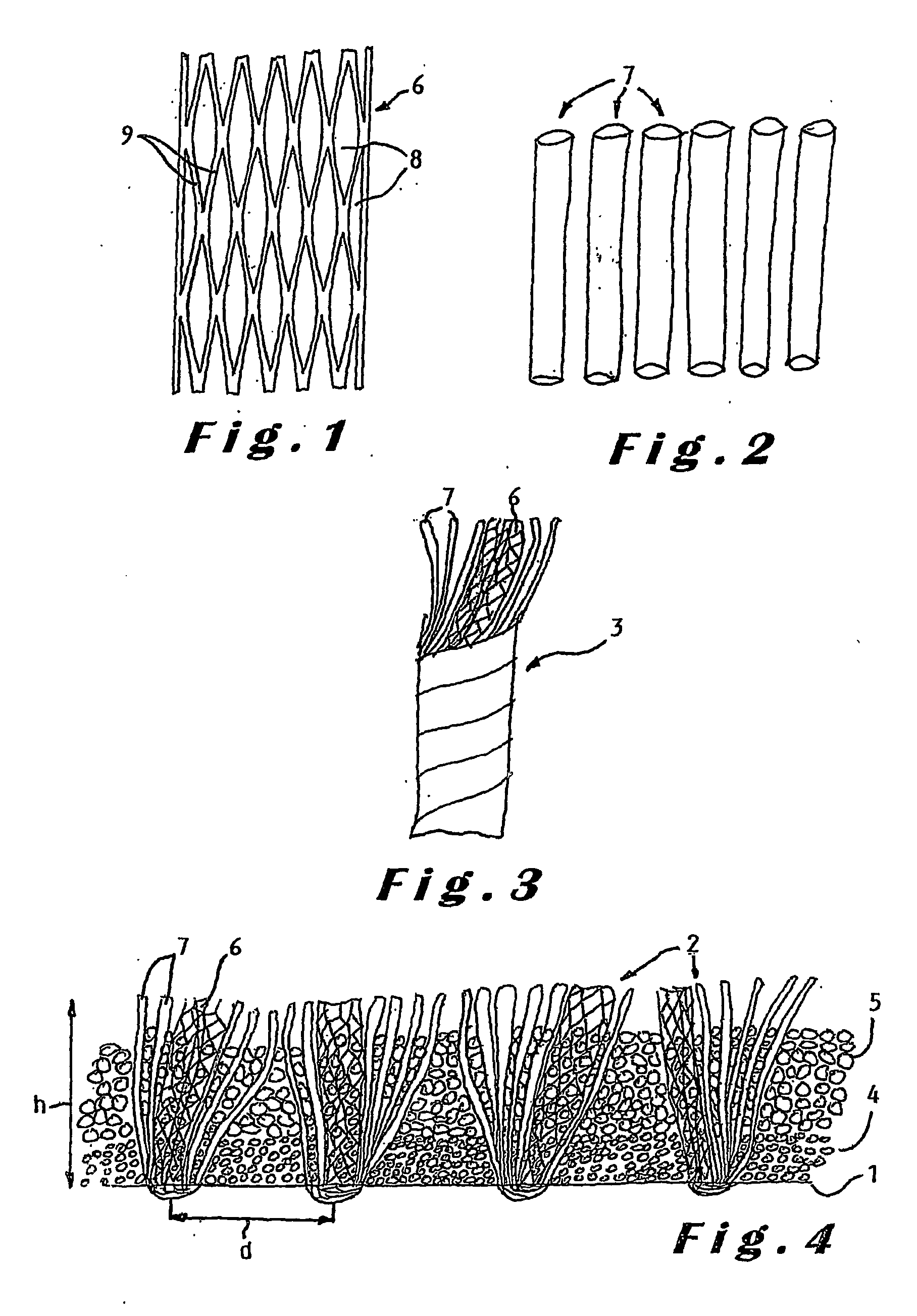
[0056] A composite yarn 3 was first made by twining one fibrillated yarn 6 around six monofilament yarns 7. The fibrillated yarn had a yarn number of 6600 dtex and a thickness of 80 μm. The slits were arranged on such mutual distances d that the filaments had varying widths, more particularly width varying between about 0.1 mm and about 1.2 mm. The monofilament yarns each had a yarn number of 1400 dtex, a thickness of 160 μm and a width of 1.4 mm. The yarn number of the composite yarn comprised 15000 dtex. The different yarns were all made of polyethylene containing UV and heat stabilisers and a green pigment. The composite yarn was tufted on a backing layer consisting of a woven polypropylene layer and a glass fibre netting. The needle distance of the tufting machine was set at ⅝″. The tufts had an average height h of about 5 cm. A latex adhesive was applied on the back of the backing layer to fix the tufts. The achieved synthetic grass is illustrated in FIG. 4. In the cross-sectio...

example 2

[0057] A composite yarn was made by twining two monotapes around four monofilament yarns. The monotape yarn had a yarn number of 2200 dtex and a thickness of 100 μm. The width of the monotape yarn was 2.5 mm. The monofilament yarn had a yarn number of 1400 dtex and a thickness of 160 μm. The width of the monofilament was 1.4 mm. The yarn number of the composite yarn was 10000 dtex. The composite yarn was tufted on a backing layer consisting of a woven polypropylene layer and a glass fibre netting. A latex adhesive was applied on the back of the backing layer to fix the tufts. The synthetic turf immediately resembled natural grass, i.e. no post-fibrillation or wear was necessary to achieve this look.

[0058] From the above given description of some preferred embodiments of the synthetic turf according to the invention, it will be clear that further modifications can be applied thereto provided they still fall within the scope of the invention as determined by the annexed claims.

[0059...


PUM

PropertyMeasurementUnit
Fractionaaaaaaaaaa
Fractionaaaaaaaaaa
Fractionaaaaaaaaaa

Abstract

The present invention provides new types of synthetic turf. The synthetic turf includes a pile fabric having a backing (1) and tufts (2) projecting therefrom. In one embodiment, at least a number of the tufts are made of a composite yarn formed by at least one fibrillated yarn (6) together with a number of individual filament yarns (7), in particular with so-called monofilament or monotape yarns. The fibrillated yarn and the individual filament yarns are preferably made of polyethylene so that the synthetic turf is sliding-friendly. In another embodiment, at least a number of the tufts are made of a composite yarn formed by monotape yarns twisted together with a number of the monofilament yarns. The monofilament and monotape yarns are preferably made of polyethylene so that the synthetic turf is sliding-friendly. The combination of a fibrillated yarn and individual filament yarns or the combination of monofilament and monotape yarns in a composite yarn allows immediate achievement of the look of natural grass, that is, without post-fibrillation, and avoids any visible difference in wear pattern between the different types of yarns. In another embodiment, the invention also provides improved particulate material for use as infill material for top-dressing a synthetic turf.

Description

FIELD OF THE INVENTION [0001] The present invention relates to a synthetic turf comprising a pile fabric having a backing and tufts projecting therefrom, the tufts comprising portions of individual filament yarns and portions of at least one fibrillated yarn which is comprised of a tape showing longitudinal slits forming laterally interconnected filaments, the individual filament yarns and the interconnected filaments having dimensions such as to resemble blades of grass. The present invention also relates to a synthetic turf comprising a pile fabric having a backing and tufts projecting therefrom, the tufts comprising portions of individual filament yarns comprising extruded monofilament yarns and monotape yarns, the monofilament yarns and monotape yarns having dimensions such as to resemble blades of grass. BACKGROUND OF THE INVENTION [0002] Synthetic or artificial turf is used more and more to replace natural grass turf on playing surfaces, in particular on sport fields like fiel...

Claims


Application Information

Patent Timeline
IPC IPC(8): B32B33/00D05C17/02E01C13/08D02G3/38
CPCY10T428/2936E01C13/08Y10T428/23993Y10T428/23957Y10T428/23921D03D15/00D10B2505/202Y10S273/13E01C2201/10
Inventor DE CLERCK, JAN
Owner DOMO ZELE
Why Eureka
Try Eureka