Fluid dynamic pressure bearing and spindle motor

a dynamic pressure bearing and spindle motor technology, applied in the direction of record information storage, record carrier construction details, instruments, etc., can solve the problems of evaporation of lubricating liquid or leakage of lubricating liquid by applying strong impact, and achieve the effect of alleviating the harm

Active Publication Date: 2006-05-11
NIPPON DENSAN CORP
View PDF4 Cites 28 Cited by
  • Summary
  • Abstract
  • Description
  • Claims
  • Application Information

AI Technical Summary

Benefits of technology

[0021] In the bearing device of the present invention, the sleeve may be made of porous materials such as oil-impregnated sintered metal material. Since the porous body can store a large amount of lubricating liquid, a retaining amount of the lubricating liquid in the bearing device is increased, so that depletion of the lubricating liquid due to evaporation or the like hardly occurs, and the bearing device with a long life can be attained. In addition, since the porous body can trap abrasion powders or the like generated in the bearing clearance, their harm can be alleviated.

Problems solved by technology

Therefore, influence of evaporation of the lubricating liquid or leakage of the lubricating liquid by applying strong impact is limited to the one end part side of the bearing device.

Method used


Image

  • Fluid dynamic pressure bearing and spindle motor
  • Fluid dynamic pressure bearing and spindle motor
  • Fluid dynamic pressure bearing and spindle motor

Examples


embodiment 1

[0037] 1-1 Description of Spindle Motor

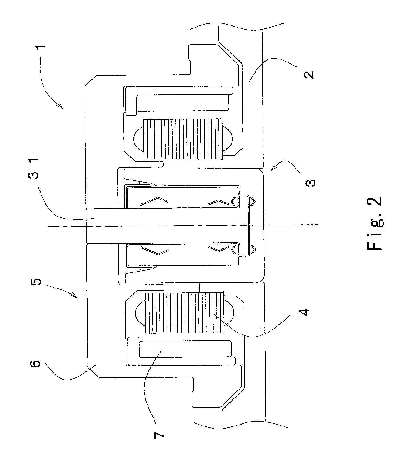
[0038]FIG. 2 is an exemplary cross-sectional view of a spindle motor 1 according to the present invention. The spindle motor 1 is assembled from a bearing device 3 according to the present invention, which is attached to a base 2, a stator 4 set on the base plate 2 surrounding the bearing device 3, and a rotor 5 attached to one end of a shaft body 31. The rotor 5 is assembled from a hub 6 and a rotor magnet 7, and the rotor magnet 7 is attached to an inner peripheral surface of a cylindrical part of the hub 6 to have a positional relationship opposed to a magnetic pole of the stator 4. By energizing this stator 4, a rotary drive force is generated. The spindle motor 1 is attached to a case of a hard disk drive or the like via the base 2.

[0039] 1-2 Entire Structure of Bearing Device

[0040]FIG. 3a) is an exemplary cross-sectional view of the bearing device 3 and FIG. 3b) is a perspective view thereof.

[0041] The bearing device 3 has a stationar...

embodiment 2

[0082] In reference to FIGS. 9 and 10, a modification 3′ of the bearing device 3 is described. FIG. 9a) is a view in which a bearing device 3′ is looked down from the upper side of the bearing. FIG. 9b) further shows a state before the cover member 35′ is attached.

[0083] Unlike the bearing device 3, the connection part 49 is located directly above the flat part 44 of the sleeve 33. In addition, a convex part 43′ is separated into two, that is, 43′a and 43′b, between which the connection part 49 is formed.

[0084]FIG. 10a) is a perspective view of this cover member 35′. Since this is formed in a method similar to the cover member 35, the slit 47 formed with the connection part 49 is also located between the two convex parts 43′a and 43′b, and extends in the axial direction.

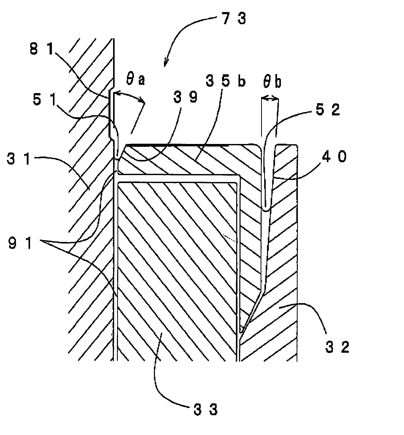
[0085]FIG. 10b) is an enlarged view of a part of the first interface, and is a cross-sectional view in a surface perpendicular to the axis line direction that includes the cover member 35′. In this case, the addit...

embodiment 3

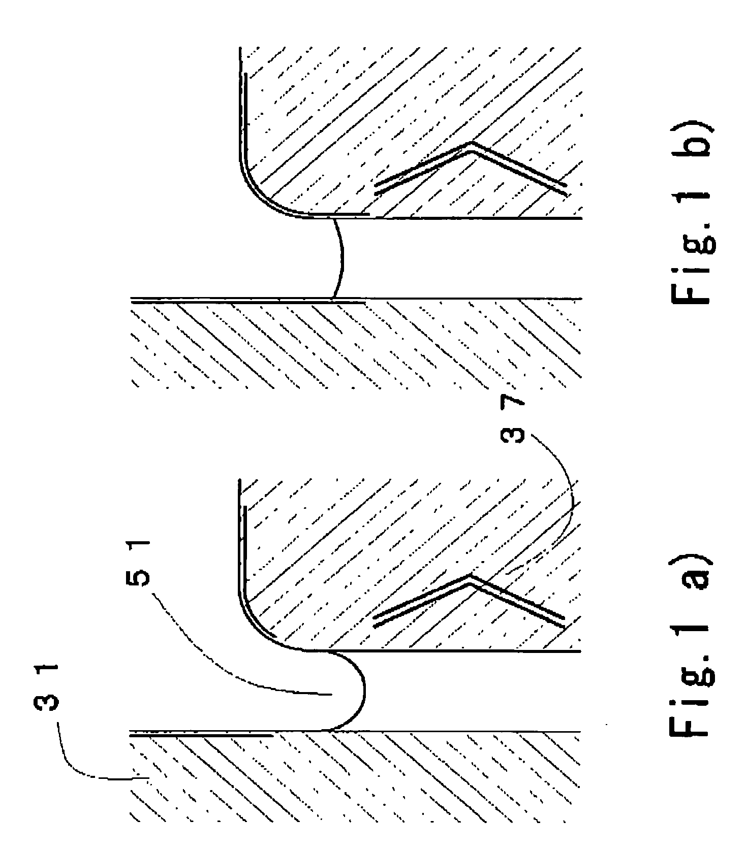
[0087] Other modifications 83, 93 of the bearing device 3 are described in reference to FIGS. 11a) and 11b).

[0088] In FIG. 11A, by reducing an external diameter of one end part of a sleeve 33′, the first tapered seal part is formed without forming the tapered part in an inner periphery of a housing 32′. In this case, for the sleeve 33′, a copper based porous sintered body is used and the tapered shape is formed simultaneously when the powder material is pressed to be shaped into a cylindrical form. The tapered part does not need to be formed by machine cutting, which reduces processing costs.

[0089] In FIG. 11b), a communicating path 42′ is formed by opening a through hole in the axial direction in the sleeve 33. Since the length of circulation root of the lubricating liquid becomes short, the circulation of the lubricating liquid becomes faster. Thereby the performance of the bearing becomes stabilized.


PUM

PropertyMeasurementUnit
contact angleaaaaaaaaaa
taper angle thetaaaaaaaaaaa

Abstract

A fluid dynamic pressure bearing having a tapered seal part provided between a sleeve and a housing, from which lubricating liquid is injected and functions as a buffer of the lubricating liquid. An end part of a radial gap between the sleeve and a shaft body is a labyrinth filled with lubricating liquid. An opening periphery is covered with an oil repellent film to prevent outflow of the lubricating liquid. These features can make the size of the tapered seal part small in the axial direction. It enables a larger radial dynamic pressure bearing mechanism to be formed and, in particular, bearing rigidity in the radial direction can be increased.

Description

FIELD OF THE INVENTION [0001] The present invention relates to a bearing device that employs a fluid dynamic pressure bearing mechanism mounted on a signal recording reproducing device such as a hard disk driving device, and a spindle motor mounting the bearing device. In particular, it relates to a thin bearing device in which a bearing thereof is small in height and a thin spindle motor. BACKGROUND ART [0002] For a spindle motor used in a signal recording and reproducing device such as a hard disk drive, various fluid dynamic pressure bearings have conventionally been used. The fluid dynamic pressure bearing is a bearing in which a lubricating liquid such as oil is interposed between a shaft body and a sleeve and a fluid pressure generated in the lubricating liquid is used as a supporting force. [0003] One example of a spindle motor using a conventional dynamic pressure bearing is illustrated in FIG. 14. In this spindle motor, a pair of radial dynamic pressure bearing mechanism 13...

Claims


Application Information

Patent Timeline
Patent Type & Authority Applications(United States)
IPC IPC(8): H02K5/16H02K7/08F16C32/06F16C33/10G11B19/20G11B33/00H02K5/167
CPCF16C17/107F16C33/103F16C33/107F16C33/745H02K5/1675F16C2370/12G11B19/2018
Inventor SUMI, SHIGEHARU
Owner NIPPON DENSAN CORP
Why Eureka
Try Eureka