Amplifier

a technology of amplifiers and amplifiers, applied in amplifiers, amplifiers with semiconductor devices/discharge tubes, amplifiers, etc., can solve the problems of difficult to adjust the impedance seen from the amplifying device b>42/b>, and achieve the effect of superior performan

Inactive Publication Date: 2006-05-11
KOKUSA ELECTRIC CO LTD
View PDF3 Cites 50 Cited by
  • Summary
  • Abstract
  • Description
  • Claims
  • Application Information

AI Technical Summary

Benefits of technology

[0052] It is, therefore, an object of the present invention to provide a modified Doherty amplifier, wherein its performance is superior to that of the conventional Doherty amplifier by implementing an appropriate impedance matching.
[0053] It is another object of the present invention to provide a modified Doherty amplifier, wherein its gain is large and its power added efficiency is at least substantially as high as that of the conventional Doherty amplifier.

Problems solved by technology

Although there are distortion compensation methods such as a feed-forward distortion compensation or a predistortion compensation, such methods have limitations to achieve the low power consumption.
However, when the conventional Doherty amplifier is applied in a high frequency operation by using a semiconductor amplifying device, the impedance seen from the amplifying device 42 cannot be easily adjusted to make it agree with the value obtained based on Doherty theory because the load line seen from the amplifying device 42 varies in accordance with the behavior of the output matching circuit 43.
However, sometimes it is difficult for a conventional matching circuit to transform Z4, which varies inwardly with reference to the center of the Smith chart, into an impedance which varies outwardly with reference to the center of the Smith chart so that the two dashed curves representing the impedance transformation paths in FIG. 3 can cross each other.
Therefore, in the conventional Doherty amplifier, the output matching circuit 43 can only implement such impedance matching as the impedance varies between ZB and ZA, thereby imposing a limitation in enhancing the performance.
Further, in the conventional Doherty amplifier, when connecting plural amplifiers serially to implement a high-gain common amplifier, the dividing loss in the divider 2 becomes high and the power efficiency or the power added efficiency becomes low.
That is, since the input impedance varies pursuant to the input level in a complicated way, it is not possible for all the electric powers of the divided signals to be used effectively.
Besides, though it is also possible to serially connect the Doherty amplifiers, multi-stage amplifier configuration causes deterioration in the performance because the Doherty amplifier includes the phase converter 3 and the Doherty combiner 6 and its characteristics vary widely with frequency.

Method used


Image

  • Amplifier
  • Amplifier
  • Amplifier

Examples


embodiment 1

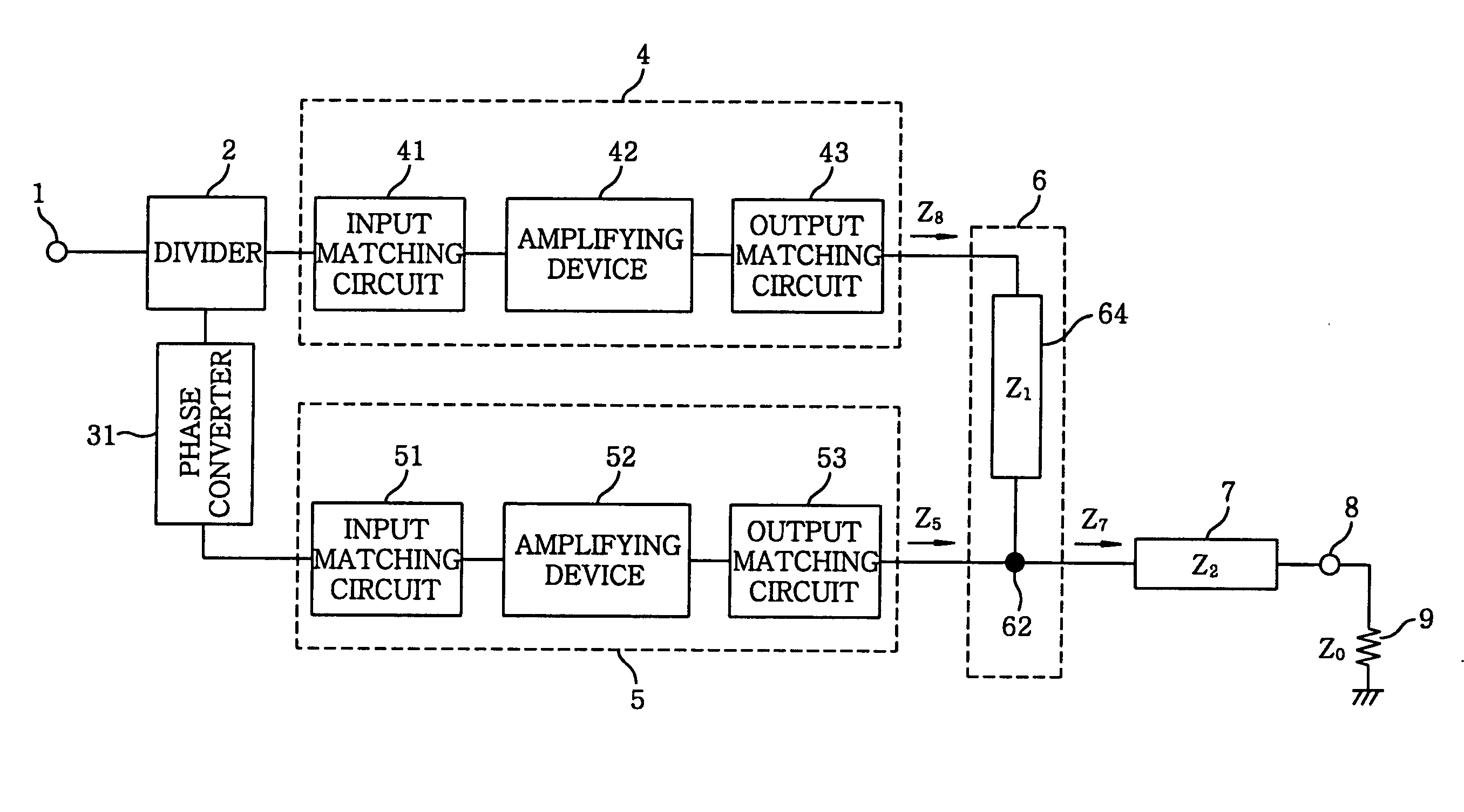
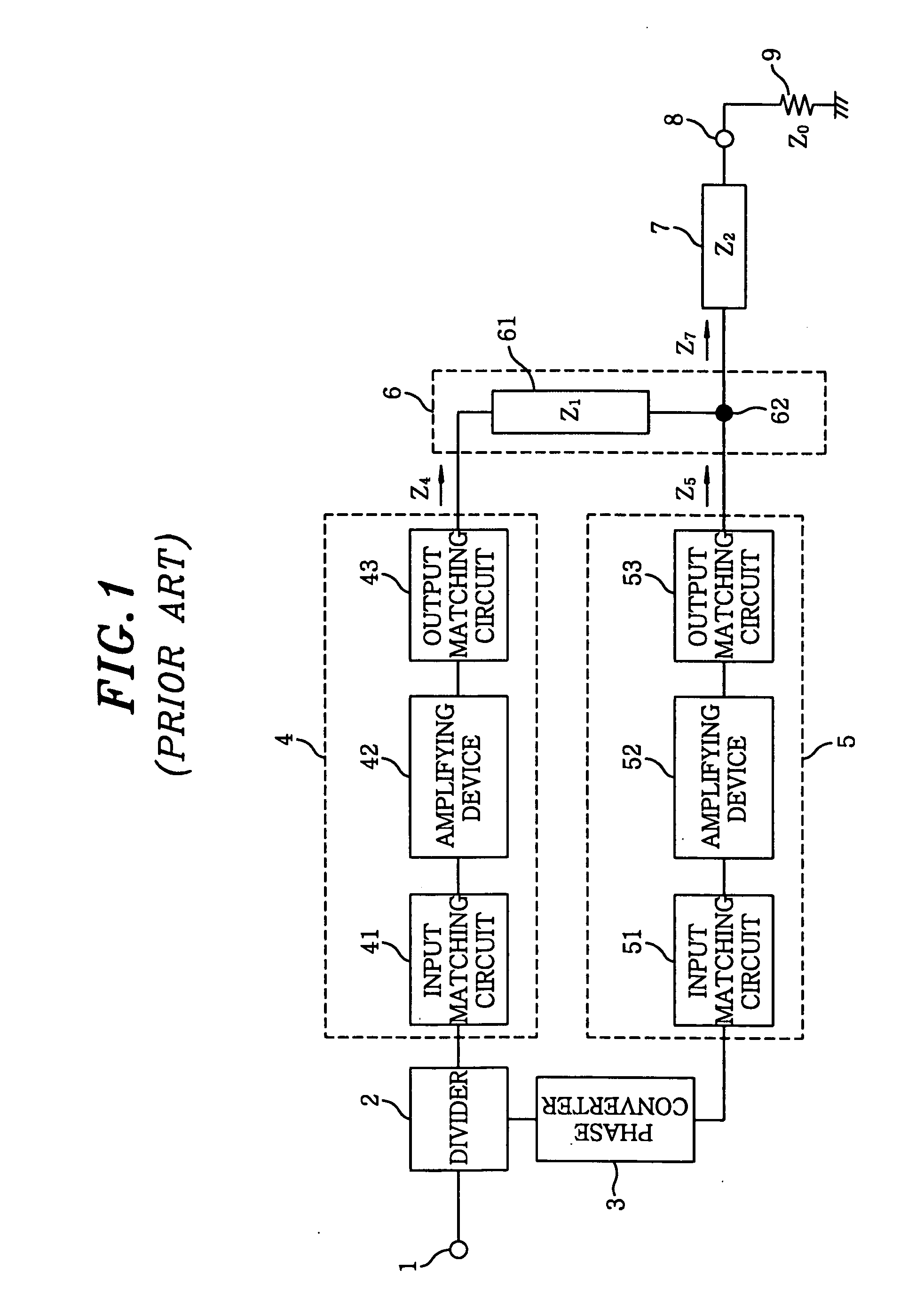
[0078]FIG. 4 describes a configuration diagram of an amplifier in accordance with a first embodiment of the present invention. An amplifier shown in FIG. 4 differs from that shown in FIG. 1 in that the λ / 4 transformer 61 is replaced with an impedance transformer 64 configured with a piece of a transmission line of an arbitrary electrical length and the phase converter 3 is replaced with a phase converter 31. Other configurations of the amplifier shown in FIG. 4 are same as those of the amplifier shown in FIG. 1, except that specifications of some components may be different.

[0079] An input signal is inputted to an input terminal 1. The inputted signal is divided by a divider 2, which is, e.g., a 3 dB coupler or a T-branch line formed on a wiring board. The phase converter 31 is, in principle, a piece of a transmission line that can generate a delay corresponding to that of the impedance transformer 64. The phase converter 31 makes a phase of an output signal of the impedance transf...

embodiment 2

[0090]FIG. 7 illustrates a configuration diagram of an amplifier in accordance with a second embodiment of the present invention. The amplifier shown in FIG. 7 differs from that shown in FIG. 4 in that an impedance transformer 65 is connected between an output matching circuit 53 and a node 62 and the phase converter 31 is replaced with a phase converter 33. Other configurations of the amplifier shown in FIG. 7 are same as those of the amplifier shown in FIG. 4, except that specifications of some components may be different.

[0091] The impedance transformer 65 transforms an output impedance Z20 of an output matching circuit 53 into a larger value Z21 when an amplifying device 52 does not operate as an input level thereof is low, thereby suppressing a signal flowing into a carrier amplifying circuit 4. The impedance transformer 65 is, for example, of an arbitrary length of a transmission line same as an impedance transformer 64.

[0092] The phase converter 33 generates a phase delay c...

embodiment 3

[0094]FIG. 8 provides a configuration diagram of an amplifier in accordance with a third embodiment of the present invention. The amplifier shown in FIG. 8 differs from that shown in FIG. 4 in that a plurality of carrier amplifying circuits or a plurality of peak amplifying circuits are provided therein, the divider 2 is replaced with a divider 21, and the λ / 4 transformer 7 is replaced with an impedance transformer 71. Other configurations of the amplifier shown in FIG. 8 are same as those in the amplifier shown in FIG. 4, except that specifications of some components may be different. This embodiment is preferable especially when two amplifiers cannot provide a large enough output power needed.

[0095] The divider 21 divides a signal inputted to an input terminal 1 by n. 4-1, 4-2, . . . 4-k (04 in FIG. 4. 5-1, 5-2, . . . 5-m are m peak amplifying circuits corresponding to the peak amplifying circuit 5 in FIG. 4. It is also possible for 4-1 to 4-k and 5-1 to 5-m are connected to an i...


PUM


Abstract

There is provided an amplifier for combining outputs of a plurality of amplifying circuits to generate an amplifier output. The amplifier includes a first amplifying circuit for operating a first amplifying device in class-AB, wherein the first amplifying circuit is one among the plurality of the amplifying circuits; a second amplifying circuit for operating a second amplifying device in class-B or class-C, wherein the second amplifying circuit is one among the plurality of the amplifying circuits; and a summing node at which an output of the first amplifying circuit is combined with an output of the second amplifying circuit via a first impedance transformer containing a transmission line of an electrical length other than λ / 4. The second amplifying device is connected to the summing node via an output matching circuit and a second impedance transformer containing a transmission line.

Description

FIELD OF THE INVENTION [0001] The present invention relates to an amplifier; and, more particularly, to a modified Doherty amplifier capable of enhancing the performance thereof especially when an amplifying device or the like whose impedance matching is difficult in a conventional Doherty amplifier is employed, or capable of enhancing the power efficiency thereof. BACKGROUND OF THE INVENTION [0002] Conventionally, when a power-amplifying radio frequency signal such as a CDMA signal or a multi-carrier signal is amplified, a distortion compensation unit is added to a common amplifier, so that an operating range of the common amplifier can be expanded to include a saturation region to achieve a low power consumption. Although there are distortion compensation methods such as a feed-forward distortion compensation or a predistortion compensation, such methods have limitations to achieve the low power consumption. Therefore, Doherty amplifiers are recently attracting attentions as a can...

Claims


Application Information

Patent Timeline
Patent Type & Authority Applications(United States)
IPC IPC(8): H03F3/68
CPCH03F1/0288
Inventor OKUBO, YOICHISUTO, MASAKITAKEDA, YASUHIROADACHI, MASARU
Owner KOKUSA ELECTRIC CO LTD
Why Eureka
Try Eureka