Protective coating for ceramic components

a technology of protective coating and ceramic components, applied in the direction of natural mineral layered products, packaging, pipes, etc., can solve the problems of rapid recession of si-based ceramic parts, limited tantalum oxide coating on si-based parts, and adverse effects of si-based ceramics

Inactive Publication Date: 2006-05-11
HONEYWELL INT INC
View PDF9 Cites 38 Cited by
  • Summary
  • Abstract
  • Description
  • Claims
  • Application Information

AI Technical Summary

Benefits of technology

[0011] According to a further aspect of the present invention, a thermally protected component comprises a silicon-based substrate; and a protective coating of crystalline composition adhered to an outer surface of the substrate, wherein the protective coating comprises an alloy including at least 50 mol % of a rare earth tantalate, scandium tantalate, yttrium tantalate, or mixtures thereof; and the balance comprising at least one oxide of an element such as Ta, Al, Hf, Ti, Zr, Mo, Nb, Ni, Sr, Mg, Si, Sc, Y, and the rare earth elements including the lanthanide series of elements.
[0012] According to still a further aspect of the present invention, a component for a gas turbine engine comprises a silicon-based substrate comprising silicon nitride or silicon carbide; and a multi-layered protective coating of crystalline composition adhered to an outer surface of the substrate, wherein the protective coating comprises at least one layer of a tantalate-containing material, and at least one layer of a silicate material, wherein the tantalate-containing material comprises at least 50 mol % of a rare earth tantalate, scandium tantalate, yttrium tantalate, or mixtures thereof; and the balance comp

Problems solved by technology

However, at operating temperatures above 1200° C., the Si-based ceramics can be adversely affected by oxidation and water vapor present in the flow stream.
Such a hostile engine environment results in rapid recession of Si-based ceramics parts.
However, there are some limitations on tantalum oxide coating on Si-based parts:
Ta2O5 is susceptible to grain growth at temperatures above 1200° C. Pronounced grain growth results in large grain microstructure, which reduces the mechanical strength of the coating and induces high local residual stresses in the coating, and causes the coa

Method used


Image

  • Protective coating for ceramic components
  • Protective coating for ceramic components
  • Protective coating for ceramic components

Examples


example 1

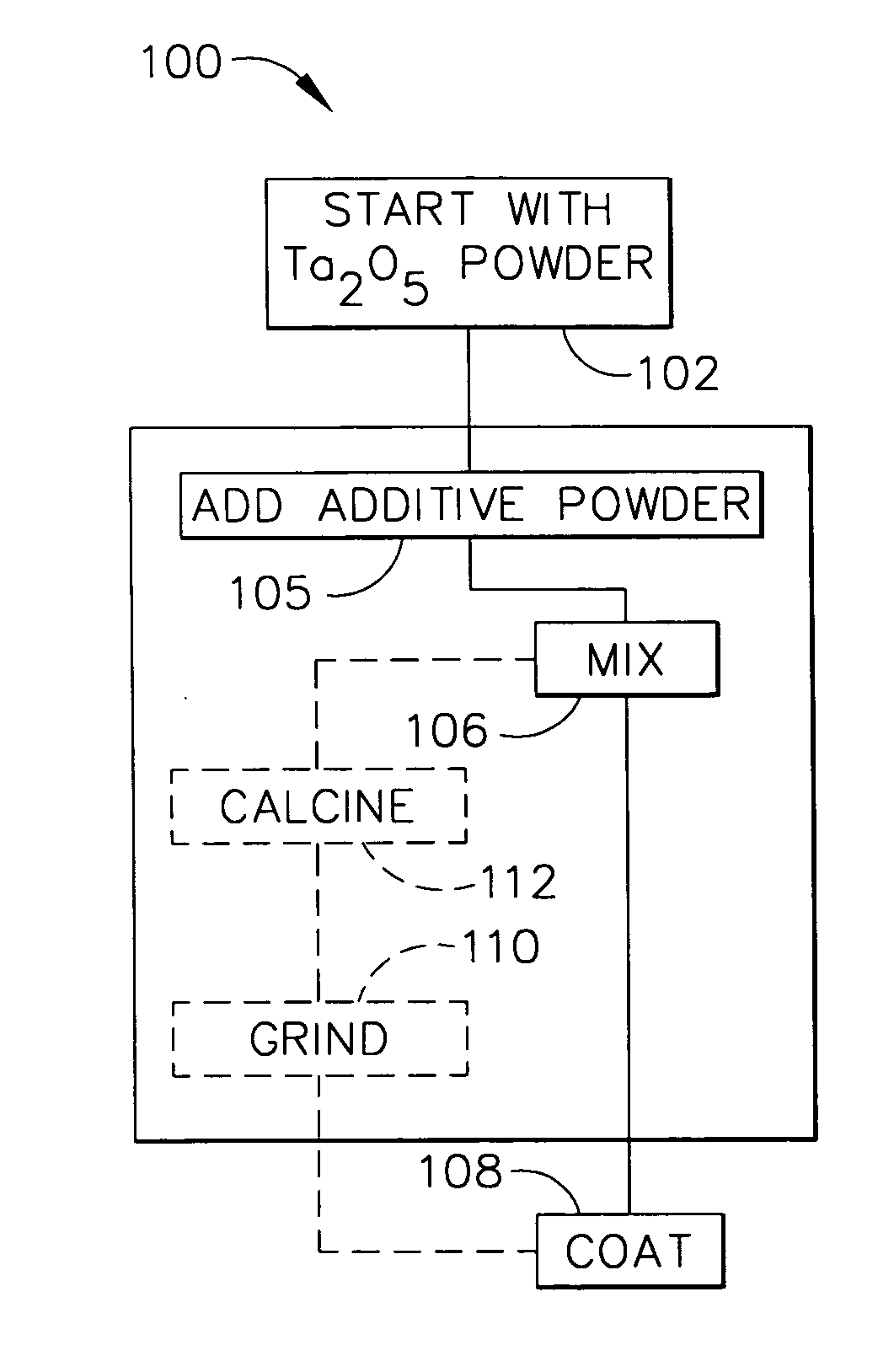
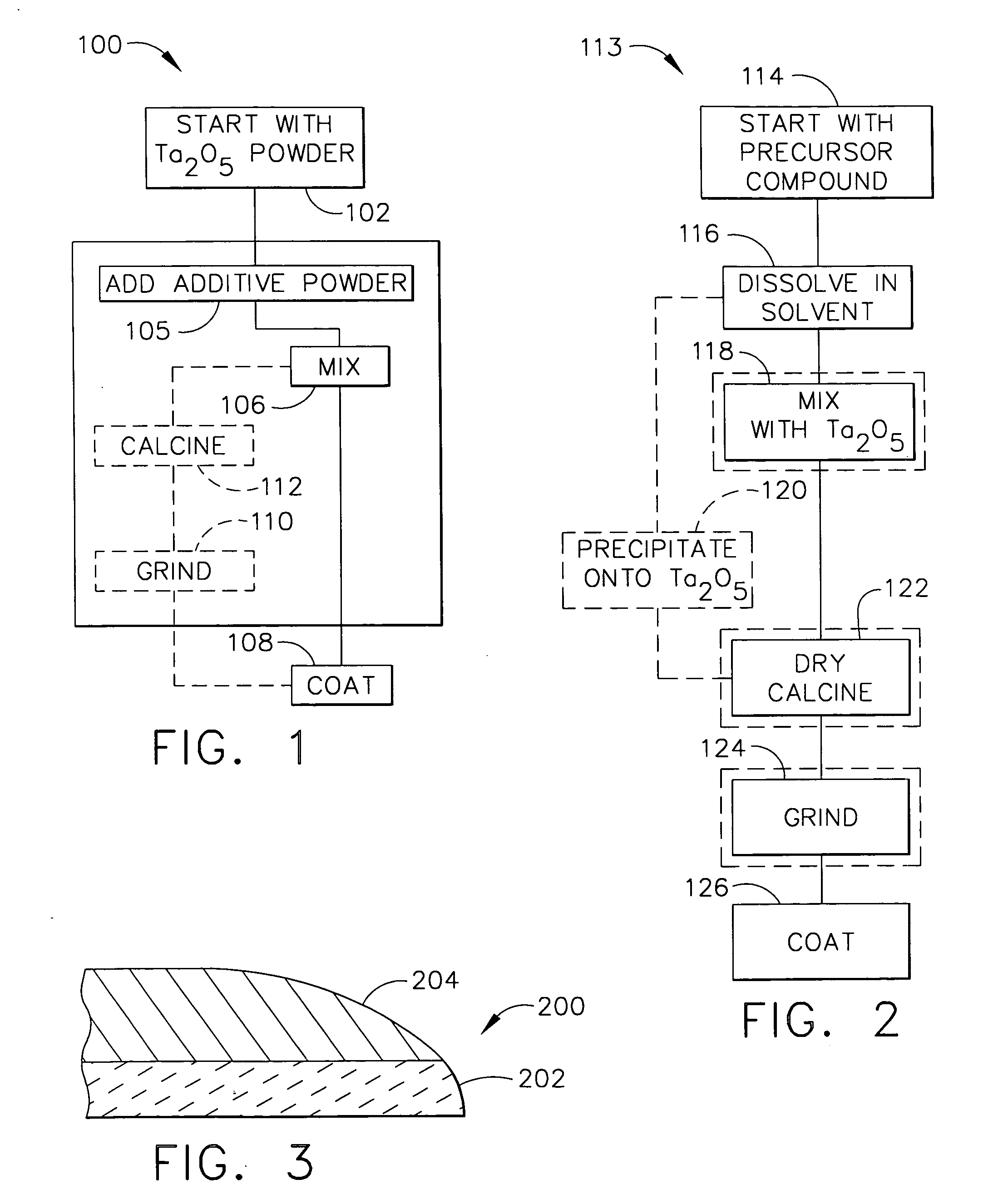
[0063] Scandium tantalate powder was prepared as follows. For each batch, about 1 kg of commercial beta Ta2O5 powder was mixed with commercial Sc2O3 powder. The exact ratio of the powders required to form ScTaO4 was used. The powders were mixed in isopropanol in a milling jar for about 2 hours before drying. The dried powder was compacted to a billet using cold issostatic pressing. This billet was then sintered at a temperature in the range of from about 1600 to 1650° C. A small sample from the sintered billet was removed and prepared for X-ray analysis, which confirmed that the sintered solid was ScTaO4.

[0064] The solid sintered billet of ScTaO4 was machined to provide a set of test bars. One such test bar was placed in a furnace at 2400° F. together with a control sample of AS800 Si3N4. Steam was passed through the furnace so that a pressure of 1 atmos of flowing steam passed over the samples. At intervals the weight of the two samples was checked. As for prior tests, the Si3N4 c...

example 2

[0065] Scandium tantalate powder was prepared as follows. In each batch, about 1 Kg of commercial beta Ta2O5 powder was mixed with commercial Sc2O3 powder in isopropanol in a milling jar for about 2 hours before drying. After drying was complete, the powder was sieved to classify the particle size to about 5 to 100 microns range in preparation for plasma spray coating. If the particle size was too fine, a calcining process was included to coarsen the particles. A coating of the above composition was then applied to coupons of silicon nitride and SiC—SiC composite substrates by an air-plasma spraying process. The silicon nitride coupons had an as-sintered surface on which the plasma coating was applied. Alternatively, a grit-blasted machine surface could have been utilized. The coupons were then degreased, and preheated to about 1000° C. by either a torch or furnace. The powder was then injected into a high velocity, high temperature plasma gun and sprayed onto the substrate to form ...

example 3

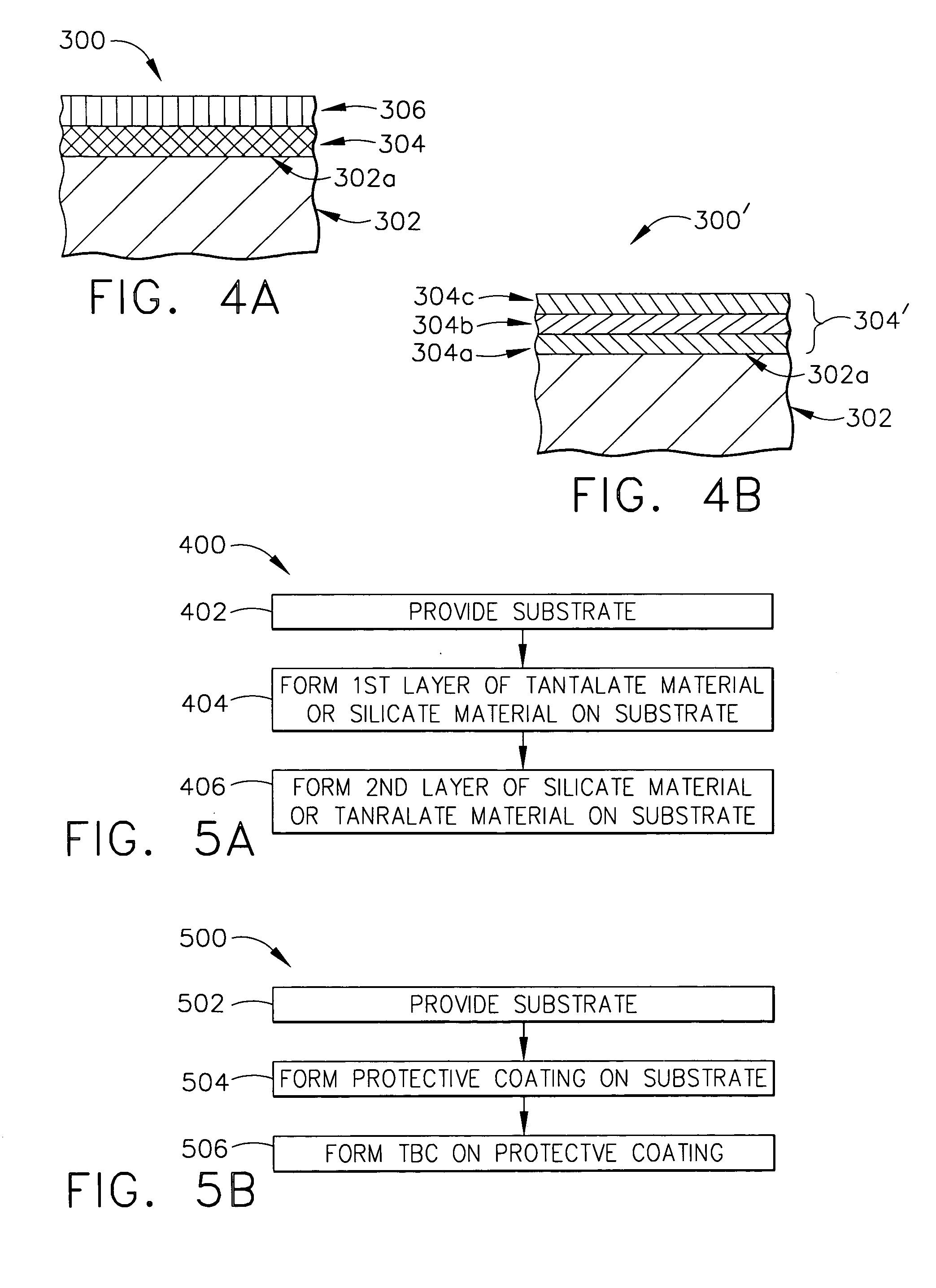
[0067] Scandium monosilicate (Sc2SiO5) powder was mixed with water to form a slurry. A sample of Si3N4 (AS800) was dipped into the slurry and allowed to dry so that it had a coating over all its surface of the Sc2SiO5. The sample was then dipped again in the slurry and allowed to dry. This process could be repeated but in this case was stopped after the 2 dips. The coating was then sintered on the part at a temperature of between 1400 to 1600° C. Scandium tantalate powder prepared as described in Example 1 was added to water to form a slurry, and the sample dipped in the scandium tantalate slurry to form a coating of scandium tantalate over the monosilicate layer. Dipping in the scandium tantalate slurry was repeated. The coating and part were then sintered as before between 1400 to 1500° C. X-ray was then used to confirm that the two layer coating thus formed was ScTaO4 on Sc2SiO5 and that other phases had not been formed.

[0068] The dual layer coating of ScTaO4 on Sc2SiO5 was test...


PUM

PropertyMeasurementUnit
Temperatureaaaaaaaaaa
Thicknessaaaaaaaaaa

Abstract

A protective coating for a component comprising a ceramic based substrate, and methods for protecting the component, the protective coating adapted for withstanding repeated thermal cycling. The substrate may comprise silicon nitride or silicon carbide, and the protective coating may comprise at least one tantalate of scandium, yttrium, or a rare earth element. The protective coating may further comprise one or more metal oxides. The coating protects the substrate from combustion gases in the high temperature turbine engine environment. The coating may be multi-layered and exhibits strong bonding to Si-based substrate materials and composites.

Description

BACKGROUND OF THE INVENTION [0001] The present invention relates to protective coatings for ceramic materials, and to methods for protecting silicon-based components. [0002] Advanced turbomachines use silicon (Si)-based ceramics such as silicon nitride, silicon carbide, and their composites for hot-section components. Due to the high temperature capability of Si-based ceramics, those ceramic turbomachines operate at higher temperatures with higher engine performance. However, at operating temperatures above 1200° C., the Si-based ceramics can be adversely affected by oxidation and water vapor present in the flow stream. Such a hostile engine environment results in rapid recession of Si-based ceramics parts. [0003] U.S. Pat. No. 6,159,553 discloses the use of tantalum oxide (Ta2O5) as coating material on silicon nitride parts. A tantalum oxide coating of 2 to 500 microns in thickness can effectively protect the surface of silicon nitride parts from oxidation and reacting with water v...

Claims


Application Information

Patent Timeline
IPC IPC(8): B31B45/00
CPCC04B41/009Y10T428/1317C04B41/52C04B41/87C04B41/89C04B2111/00982C23C26/00C23C30/00Y02T50/67C04B41/5027Y10T428/13Y10T428/131C23C28/042C04B41/4527C04B41/5059C04B41/5066C04B41/522C04B41/4539C04B41/5024C04B41/5042C04B35/565C04B35/584C04B35/806Y02T50/60
Inventor RAYBOULD, DEREKLI, CHIEN-WEISCHENK, BJOERNSTRANGMAN, THOMAS E.
Owner HONEYWELL INT INC
Why Eureka
Try Eureka