
Membrane treatment method

Active Publication Date: 2006-05-25
GM GLOBAL TECH OPERATIONS LLC
View PDF2 Cites 3 Cited by
  • Summary
  • Abstract
  • Description
  • Claims
  • Application Information

AI Technical Summary

Benefits of technology

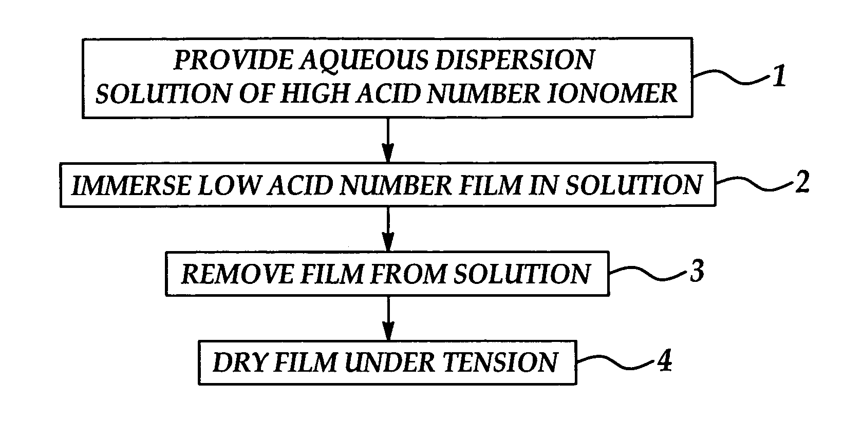
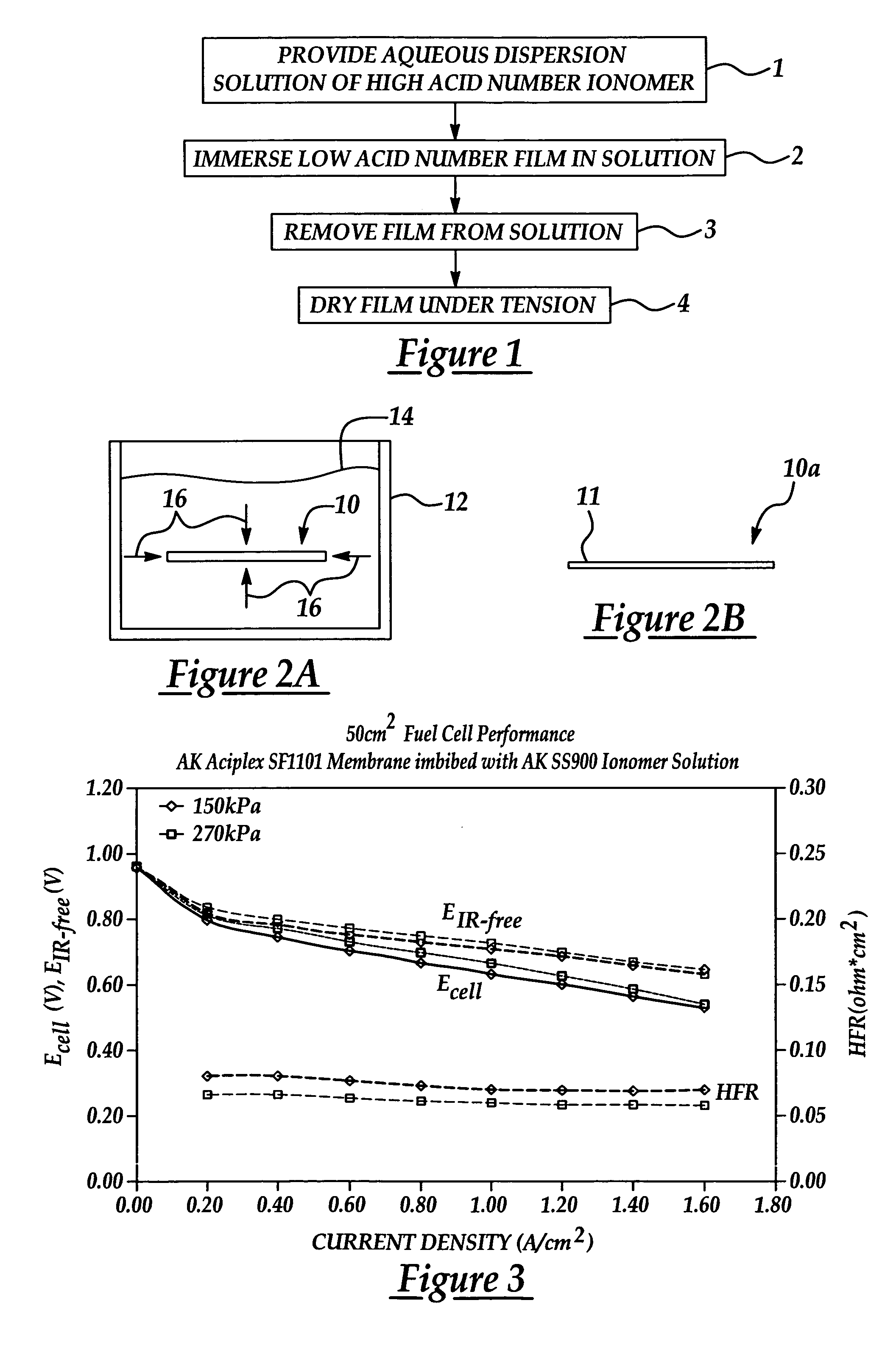
[0011] The present invention is generally directed to a novel method of treating a membrane, such as a perfluorosulfonic acid (PFSA) membrane, with a low equivalent weight perfluorosulfonic acid dispersion (or solution) for use as a polyelectrolyte membrane (PEM) in a fuel cell. Immersion of the membrane in the low equivalent weight PFSA dispersion enhances the proton-conducting capability of the membrane during functioning of the fuel cell. The method includes providing, for example but not limiting to, a high acid number PSFA dispersed or dissolved in an aqueous hydroxylated-hydrocarbon aqueous solution, immersing a preformed low acid number PSFA, or other membrane, in the solution, and then, after removal, drying the membrane under tension. Between about 5 and 50 wt. % of the high acid number PFSA diffuses into the low acid number membrane, as calculated on the basis of the dry weight increase of the membrane. Compared with untreated low acid number ionomer membranes, the modified membranes show higher acid numbers and improved proton conductivity. Other advantages realized from the immersion treatment include the preparation of thin membrane films with reduced internal stresses, reduced and thus improved electrical resistance due to the smaller dimensional thickness, reduced and therefore improved electrical contact resistance between the treated membrane and the catalyst layer, and improved water diffusion for maintaining uniform membrane hydration.

Problems solved by technology

Irreversible damage to the fuel cell will occur if the membrane dries out.
The resultant electro-osmotic drag results in the drying out of the anode side of the membrane, especially as large numbers of hydrated protons move through the membrane.
Moreover, the presence of liquid water in automotive fuel cells is unavoidable because appreciable quantities of water are generated as a by-product of the electrochemical reactions during fuel cell operation.
Furthermore, saturation of the fuel cell membranes with water can result from rapid changes in temperature, relative humidity, and operating and shutdown conditions.
However, excessive membrane hydration results in flooding, excessive swelling of the membranes and the formation of differential pressure gradients across the fuel cell stack.
PFSA membranes with high acid numbers (or low equivalent weights) have enhanced proton conductivity at reduced relative humidity, but the mechanical properties of these membranes (especially with the high acid numbers) are compromised because of swelling due to high water uptake.
The in-plane swelling of extruded membranes is further complicated because the membranes typically swell less in the machine process direction (the x-axis) as compared to the transverse direction (the y-axis) of the film.
Non-uniform membrane swelling introduces the possibility of uneven, pressure-related stress failure mechanisms in fuel cell stacks.
As the membranes dry out at reduced humidity, proton conductivity deteriorates rapidly.
When fuel cells operate near the boiling point of water, elevated pressures are required to maintain membrane hydration, and the compressors required are a parasitic drain on the energy produced.
PSFA membranes with high acid numbers (or low equivalent weights) are expected to have enhanced proton conductivity at reduced relative humidity, but the mechanical properties of these membranes (with the high acid numbers) are compromised because of increased water uptake and swelling.
However, methods are needed to perform the cross-linking reactions after the film is made; otherwise, film manufacture is difficult.

Method used


Image

  • Membrane treatment method
  • Membrane treatment method

Examples


example i

[0025] An Aciplex membrane film (1101) and an aqueous dispersion or solution (SS900 / 05) were obtained from Asahi-Kasei. The membrane film was immersed in the aqueous dispersion solution, then removed from the solution and dried under tension. The membrane film increased in weight by 15.4% after drying. The overall amount of ionomer from the SS900 / 05 dispersion solution in the membrane film was 15.4 wt. %. The treated membrane film was about one-half the thickness of the pre-treated membrane film.

example ii

[0026] An Aciplex membrane film (1101) and an aqueous dispersion solution (SS-700) were obtained from Asahi-Kasei. The membrane film was immersed in the aqueous dispersion or solution, removed from the solution and dried under tension, respectively. The membrane film increased in weight by 13.3% after drying for 16 hours at between 150 and 170 degrees C. If lower temperatures are used, the SS-700 component re-dissolves in water. The overall amount of 700 equivalent weight ionomer from the SS-700 dispersion solution in the membrane film was 13.3 wt. %. The treated membrane film was about one-half the thickness of the pre-treated membrane film.

[0027] Tables (I) and (II) below present, in tabulated form, electrical performance data for fuel cells which incorporate the treated PFSA membrane films of the present invention as the polymer electrolyte membrane (PEM) in the fuel cells.

TABLE IHigh Pressure Performance (270 kPaabs)i(A / cm2)Ecell (V)sd_EcellHFR (ohm*cm2)sd_HFREiR-free (V)sd_E...


PUM

PropertyMeasurementUnit
Percent by massaaaaaaaaaa
Equivalent massaaaaaaaaaa

Abstract

A method of enhancing electrical performance of a membrane for a fuel cell is disclosed. The method includes providing a perfluorosulfonic acid (PFSA) ionomer in an aqueous hydroxylated hydrocarbon aqueous solution. The PFSA dispersion or solution has an acid number the same or higher than an acid number of the membrane. The membrane is immersed in the solution such that the high acid number PFSA dispersion diffuses into the membrane. After immersion, the removed membrane is then dried under tension.

Description

FIELD OF THE INVENTION [0001] The present invention relates to fuel cells which generate electricity to power vehicles or other machinery. More particularly, the present invention relates to a method of treating a membrane such as a perfluorosulfonic acid membrane with, for example, a low equivalent weight perfluorosulfonic acid dispersion or solution, for use as a polyelectrolyte membrane (PEM) used in a fuel cell in order to enhance the proton-conducting capability of the membrane. The present invention also relates to treating a polyelectrolyte membrane with a perfluorosulfonic acid dispersion or solution, for use as a PEM in a fuel cell in order to produce thin membranes for improved water management, water vapor transfer, and reduced membrane electrical resistance. Moreover, the present invention allows for an improved membrane with reduced internal mechanical stresses and provides a means to reduce the electrical contact resistance between the (treated) membrane and the cataly...

Claims


Application Information

Patent Timeline
IPC IPC(8): H01M8/10C08J5/22
CPCC08J5/2237H01M8/1023H01M8/1039H01M8/106H01M8/1081H01M2300/0082H01M2300/0088Y02E60/521C08J5/2281C08J2327/12Y02E60/50Y02P70/50
Inventor FULLER, TIMOTHY J.DOBULIS, BEBA T.
Owner GM GLOBAL TECH OPERATIONS LLC
Learn More