Irradiation system with ion beam/charged particle beam

a technology of ion beam and charge beam, which is applied in the field of irradiation system with ion beam/charged particle beam, can solve the problems of insufficient suppression of leakage magnetic field of analyzing electromagnet, bad influence of charge-up suppression plasma shower electrons on the neutralization effect of wafers,

Inactive Publication Date: 2006-06-01
SENCORP
View PDF4 Cites 11 Cited by
  • Summary
  • Abstract
  • Description
  • Claims
  • Application Information

AI Technical Summary

Benefits of technology

[0018] According to the fourth aspect of this invention, in the irradiation system with ion beam / charged particle beam according to the first or the second aspect, the deflection magnet comprises a main coil, a secondary coil, and a cancel correction coils which cancel leakage magnetic-field and provides uniformity of the BL product by balancing currents supplied to the coils.

Problems solved by technology

However, using the energy filter including the electromagnet with the large hollow-portion, there is a possibility that its leakage magnetic field gives bad influence to the wafer neutralization effect of charge-up suppression plasma shower electrons.
However, there is a problem that although the conventional method of suppressing the leakage magnetic field of the analyzing electromagnet by the use of the field clamp is suitable for the analyzing electromagnet having a small opening (or hollow-portion) with the narrow magnetic gap, it is insufficient for suppressing a leakage magnetic field from an analyzing electromagnet having a large opening (or hollow-portion).
Further, there is a problem that the conventional method of suppressing the leakage magnetic field by the use of the superconductive material is applied to a C-shaped magnet but is not applicable to an analyzing electromagnet having a hollow-portion at its center.
In addition, there is also a problem that such a superconductive material suppresses a leakage magnetic field leaking to both inner and outer sides in beam bending radial directions but cannot suppress a leakage magnetic field in a longitudinal direction, i.e. a leakage magnetic field directed toward a wafer.
Moreover, there is a problem that the conventional method of uniforming the magnetic field distribution aims at only the magnetic field distribution in the opening (or hollow-portion) of the analyzing electromagnet but takes into account nothing about a leakage magnetic field.

Method used


Image

  • Irradiation system with ion beam/charged particle beam
  • Irradiation system with ion beam/charged particle beam
  • Irradiation system with ion beam/charged particle beam

Examples


Embodiment Construction

[0034] Now, the best mode for carrying out the invention will be described in detail with reference to the drawings.

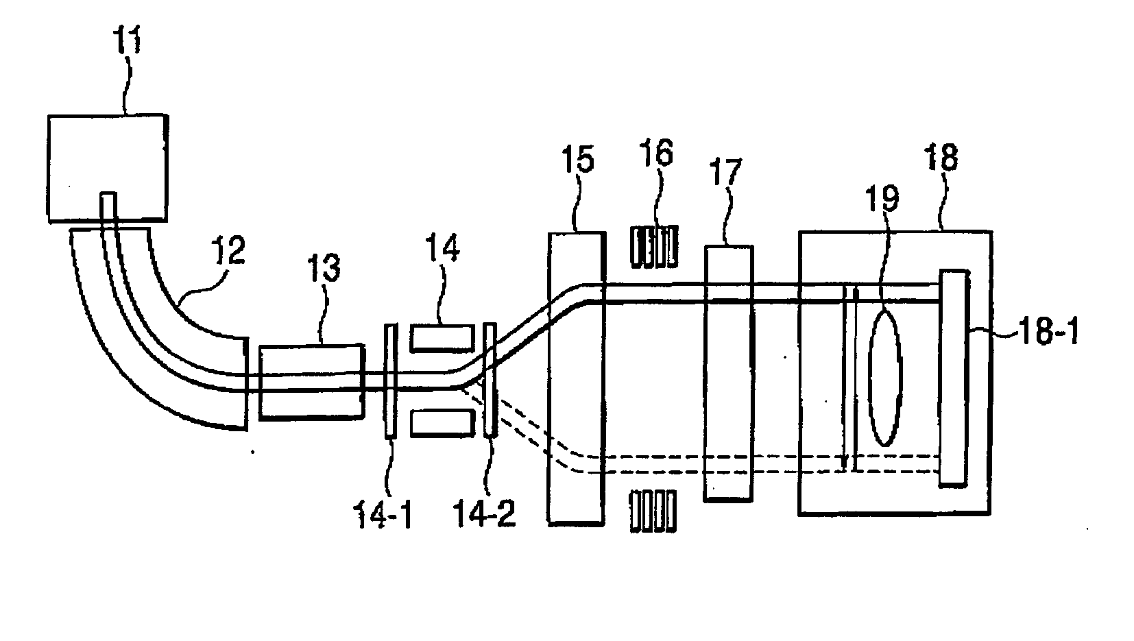
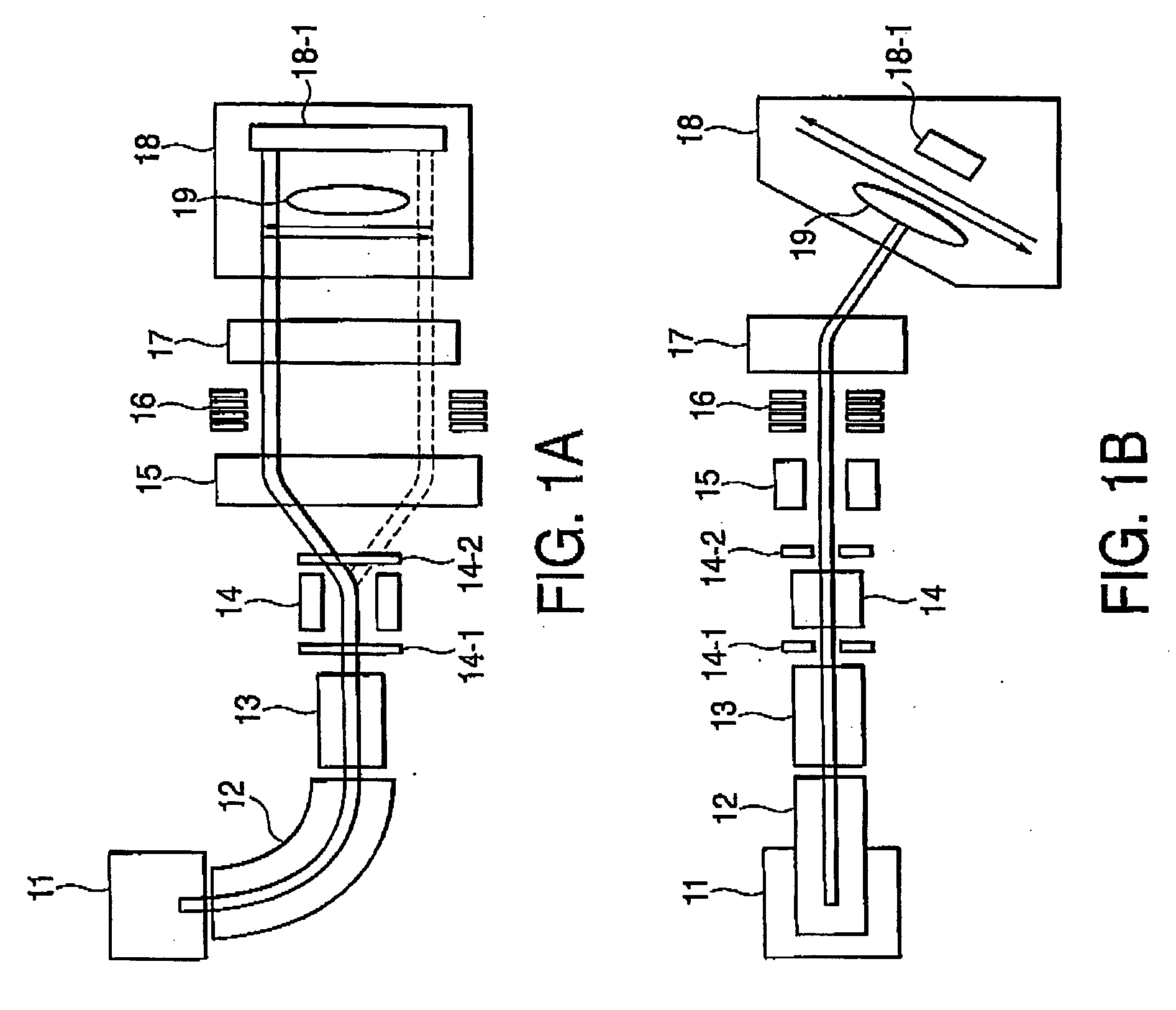
[0035]FIGS. 1A and 1B are a plan view and a side view, respectively, showing a schematic structure of an irradiation system with an ion beam / charged particle beam (hereinafter abbreviated as a “irradiation system with beam”) according to an embodiment of this invention.

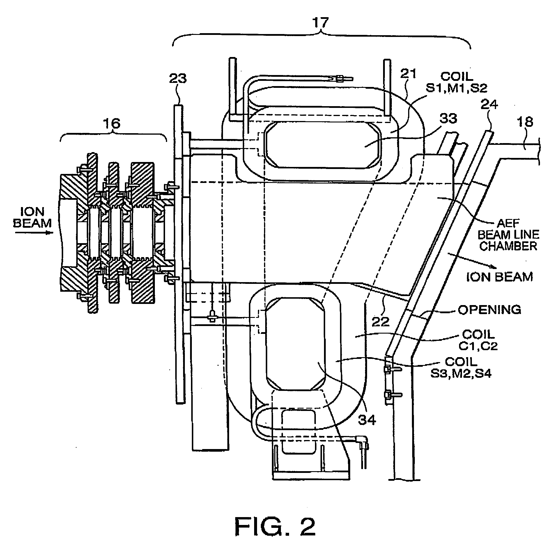
[0036] The illustrated irradiation system with a beam comprises an ion source 11, a mass analysis magnet device 12, a beam transformer 13, a deflector for scanning 14, a P (Parallelizing)-lens 15, acceleration / deceleration electrodes (in an A / D columns) 16, an angular energy filter (AEF) 17, and a process vacuum chamber 18.

[0037] In this irradiation system with a beam, ions or charged particles generated in the ion source 11 are extracted through extraction electrodes (not illustrated) as an ion beam or a charged particle beam (hereinafter referred to as a “beam”). The extracted beam is subjected to a...


PUM


Abstract

In an irradiation system with an ion beam/charged particle beam, an ion beam/charged particle beam is deflected by an energy filter for the energy analysis and then a wafer irradiated with the beam. The energy filter controls the spread of magnetic field distribution caused by a deflection magnet, cancels a leakage magnetic field in the longitudinal direction, and bends the ion beam/charged particle beam at a uniform angle at any positions overall in scanning-deflection area.

Description

[0001] This application claims priority to prior Japanese patent application JP 2004-34678, the disclosure of which is incorporated herein by reference. BACKGROUND OF THE INVENTION [0002] This invention relates to an irradiation system with an ion beam / charged particle beam and, in particular, relates to an energy filter for use therein. [0003] An irradiation system with an ion beam / charged particle beam (also called an ion implantation system; hereinafter referred to simply as a “irradiation system with a beam”) is a system for applying a mass analysis to ions or charged particles extracted from a beam source to thereby select only a necessary ion species or necessary charged particles and irradiating a wafer with the beam. [0004] Among this type of irradiation systems with the beam, there is available one having, in addition to a mass analyzer, an energy filter called an angular energy filter (AEF) in order to more accurately implant ions or charged particles into a wafer. [0005] ...

Claims


Application Information

Patent Timeline
Patent Type & Authority Applications(United States)
IPC IPC(8): B01D59/44
CPCH01J37/05H01J37/3171H01J49/26H01L21/265
Inventor YAGITA, TAKANORI
Owner SENCORP
Why Eureka
Try Eureka