
INL curve correction in a pipeline ADC
a pipeline and curve correction technology, applied in the field of integral non linearity errors in the pipeline analog to digital converter, can solve the problems of linearity errors, errors which manifest, and prone to architecture dependent integral non linearity (inl) errors, and achieve the effect of reducing non linearity errors
- Summary
- Abstract
- Description
- Claims
- Application Information
AI Technical Summary
Benefits of technology
Problems solved by technology
Method used
Image

Examples
first embodiment
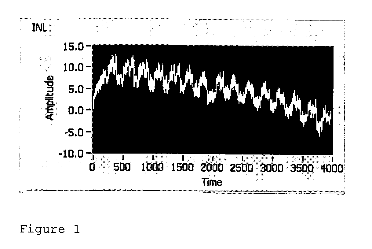
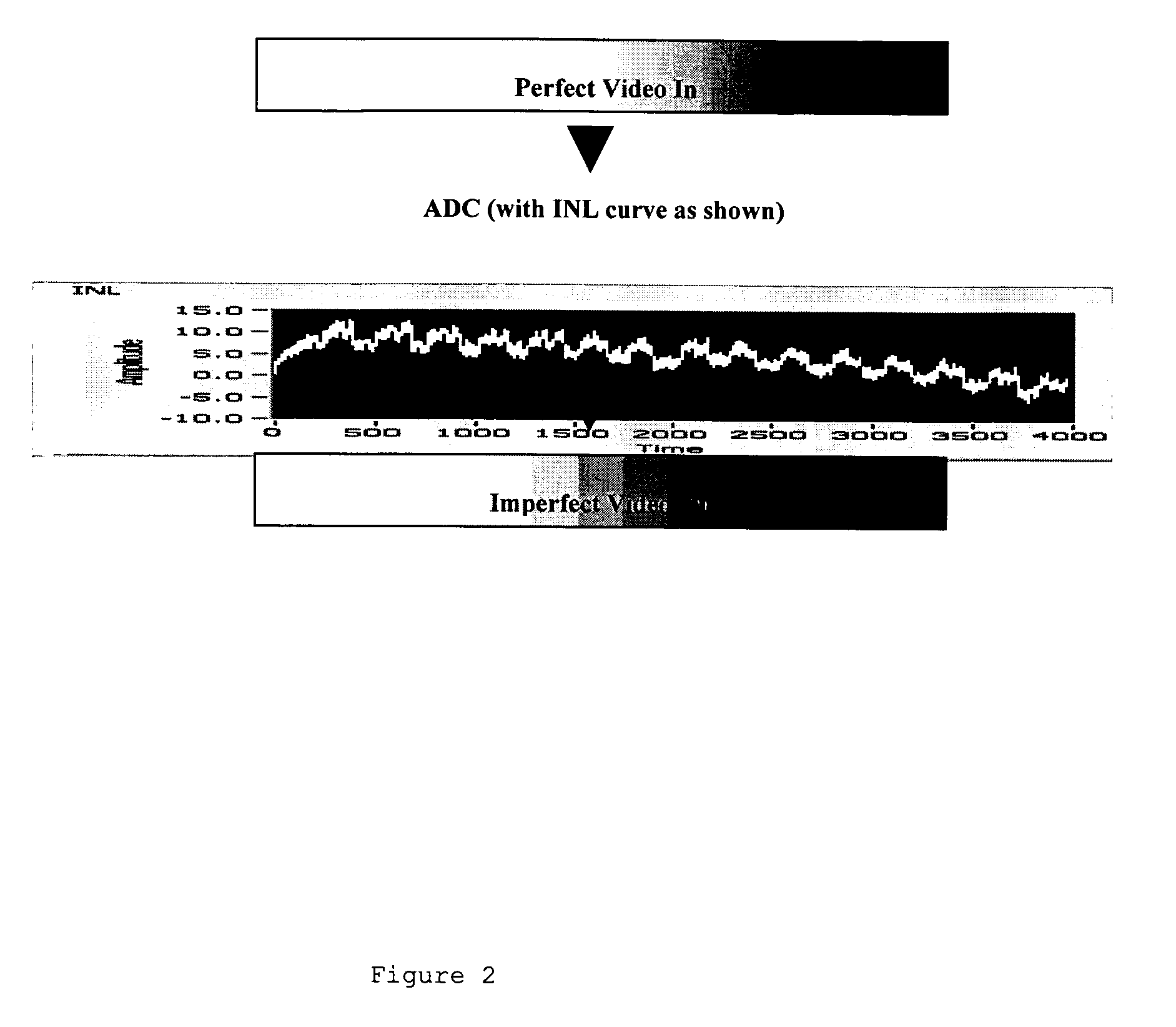
[0074]FIG. 3 shows a typical real transfer function of a converted digital signal for an ADC which has INL errors. It will be appreciated that this transfer function with the INL errors resembles a staircase waveform. It also shows an ideal transfer function of a converted digital signal i.e. that of a converted digital signal exhibiting no INL errors. The method of the present invention processes the real signal so that the resulting converted digital signal approximates the ideal transfer function when viewed by the human eye. In brief, this embodiment adds an analog dither signal at the input to the ADC and subtracts it in the digital domain.
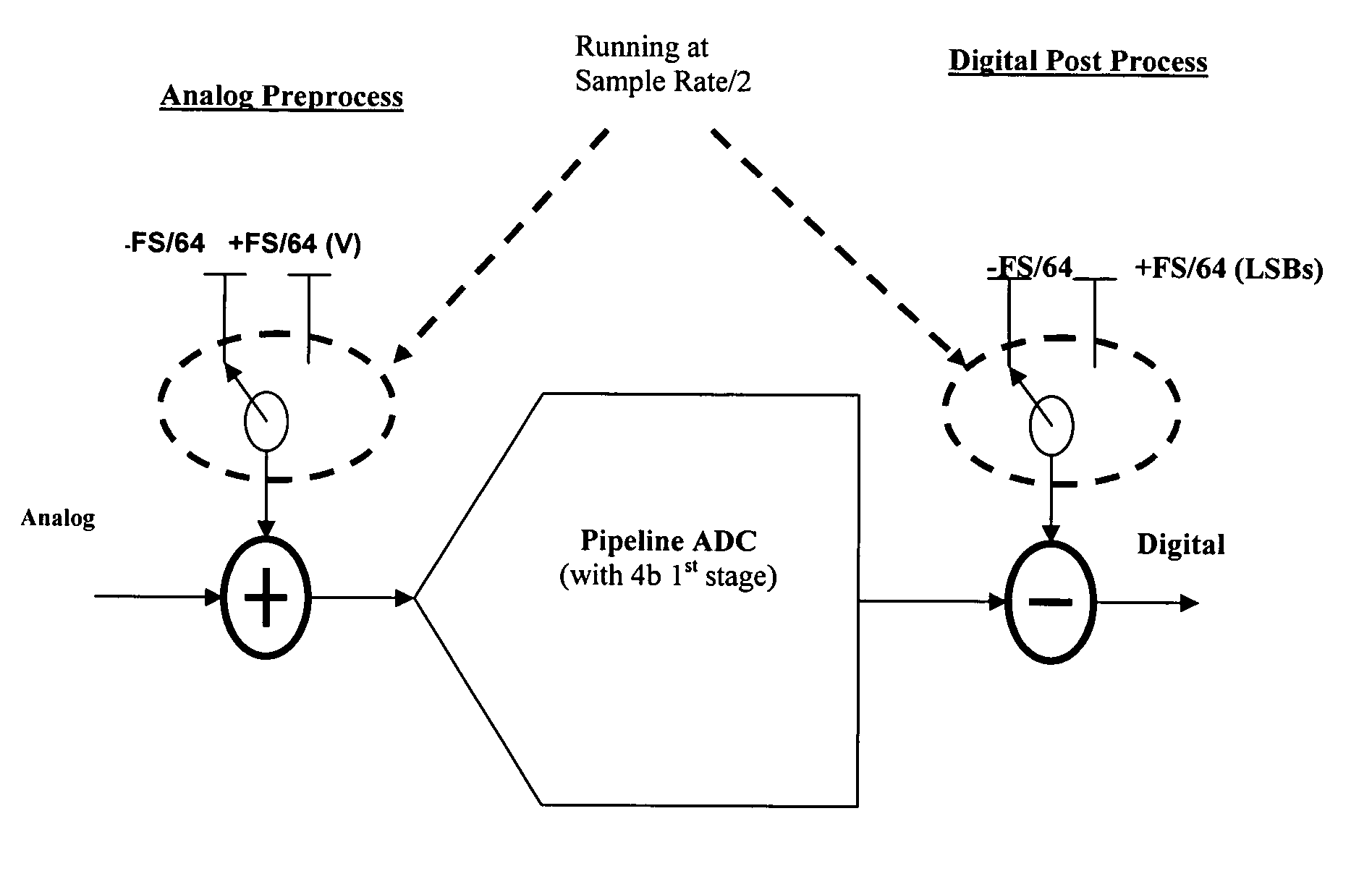
[0075] The first step of the method of the first embodiment of the invention is to preprocess the analog input signal, as shown in FIGS. 3 and 4. This involves adding an analog bias at the input of the ADC, also known as an analog dither signal. In the described embodiment, the bias is a square wave and has a frequency of Fs / 2 (i.e. the sampl...
second embodiment
[0097] The circuit of the invention results in the reduction of INL errors, due to the fact that in a pipeline ADC the first stage flash makes an estimate or “guess” or a rough 4 bit digitization of the input signal. This is permitted to be highly inaccurate. This initial estimate is then subtracted from the input signal and the value gained up (Vout=8*(Vin−estimate) before being passed to the residual ADC where the process starts all over again. These estimates are recombined in logic known as “digital error correction” to give the correct digital converted output. A key feature of pipeline ADCs is that every digitization is allowed to be very rough. The reason for that is that any error in this estimate is built into the analog residue sent to the residual ADC where it gets accommodated downstream. This is known as redundancy.
[0098] It will be appreciated therefore that all the accuracy of the pipeline ADC is carried in the MDACs, while the flashes can be highly inaccurate. For ex...
PUM
 Abstract
Description
Claims
Application Information