Polymer electrolyte fuel cell

a fuel cell and electrolyte technology, applied in the field of polymer electrolyte fuel cells, can solve the problems of gas diffusivity disturbance, increased pressure loss of the unit cell b>101/b>, and gas diffusion layer buckled, etc., to achieve increase electrical resistance, and easy and reliably embodied

Inactive Publication Date: 2006-06-01
PANASONIC CORP
View PDF1 Cites 27 Cited by
  • Summary
  • Abstract
  • Description
  • Claims
  • Application Information

AI Technical Summary

Benefits of technology

[0029] In a polymer electrolyte fuel cell of the present invention such as the above, by forming a structure such as the above in at least one of the stacked separator plates, the following polymer electrolyte fuel cell can be easily and reliably embodied: increase in electrical resistance (contact resistance) between a gas diffusion layer of an anode and an anode side separator plate, and between a gas diffusion layer of a cathode and a cathode side separator plate can be suppressed, while sealing effect can be displayed without gas leak by compressing a gasket sufficiently, and increase in pressure loss due to close of a gas flow path and damage to a polymer electrolyte membrane by the gas diffusion layer can be avoided.
[0030] According to the present invention, the following polymer electrolyte fuel cell can be easily and reliably embodied: even a sealing effect is displayed without gas leak by compressing a gasket sufficiently, increase in electrical resistance (contact resistance) between a gas diffusion layer of an anode and an anode side separator plate, and between a gas diffusion layer of a cathode and a cathode side separator plate can be suppressed, and increase in pressure loss due to close of a gas flow path and damage to a polymer electrolyte membrane by the gas diffusion layer can be avoided.

Problems solved by technology

In such case, gas diffusivity is disturbed to create problems: pressure loss of the unit cell 101 is increased, and the gas diffusion layer is buckled to damage the MEA.

Method used


Image

  • Polymer electrolyte fuel cell
  • Polymer electrolyte fuel cell
  • Polymer electrolyte fuel cell

Examples


embodiment 1

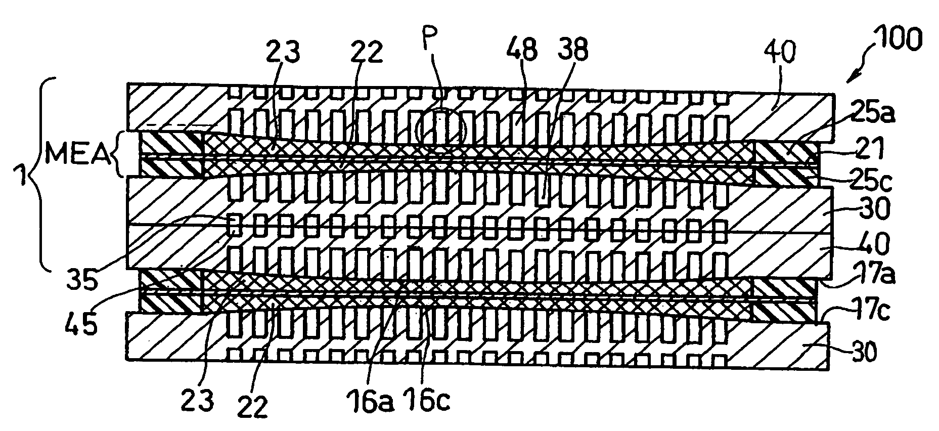
[0044]FIG. 1 is a schematic sectional view illustrating a basic structure of a polymer electrolyte fuel cell in Embodiment 1 of the present invention. As shown in FIG. 1, a unit cell 1, i.e., a basic structure of the polymer electrolyte fuel cell 100 in this embodiment, mainly comprises a polymer electrolyte membrane 21 which selectively transfers cation (hydrogen ion), and a pair of electrodes (anode and cathode) 22, 23 disposed on both sides of the polymer electrolyte membrane 21. A cathode 22 and an anode 23 are composed of a catalyst layer comprising a mixture of a carbon powder carrying an electrode catalyst (platinum for example) and a hydrogen ion conductive polymer electrolyte, and a gas diffusion layer comprising for example a water repellent treated carbon paper, formed on outside of the catalyst layer and having both gas permeability and electron conductivity.

[0045] Then, gas sealing members such as gaskets 25a and 25c are disposed to sandwich the polymer electrolyte mem...

embodiment 2

[0070] Next, a polymer electrolyte fuel cell in Embodiment 2 of the present invention will be described. In this polymer electrolyte fuel cell in Embodiment 2, the combination of the anode side separator plate 30 and the cathode side separator plate 40 in the polymer electrolyte fuel cell 100 in Embodiment 1 shown in FIG. 1 is replaced by a single composite separator plate 50, as shown in FIG. 8, and the construction except for the composite separator plate 50 is the same as that of the polymer electrolyte fuel cell 100 in Embodiment 1. FIG. 8 is a schematic sectional view illustrating a basic structure of the polymer electrolyte fuel cell in Embodiment 2 of the present invention.

[0071] In the following, the composite separator plate 50 provided in a polymer electrolyte fuel cell 200 in Embodiment 2 (a separator plate in Embodiment 2 of the present invention) is described. FIG. 9 is a front view enlarging a main portion of the composite separator plate 50 in the polymer electrolyte...

example 1

[0084] A polymer electrolyte fuel cell of the present invention comprising a unit cell 1 was made by using the cathode side separator plate 30 and the anode side separator plate 40 in the above Embodiment 1.

[0085] First, a cathode catalyst-carrying carbon powder (Pt:50 weight %) is obtained by causing a conductive carbon powder having an average primary particle size of 30 nm (Ketjen black EC (a product name): product of AKZO Chemie B.V., the Netherlands) to carry platinum particles having an average particle size of 3 nm. Also, an anode catalyst-carrying carbon powder (Pt:25 weight %, Ru:25 weight %) is obtained by causing the same conductive carbon powder as the above to carry platinum particles and ruthenium particles each having an average particle size of 30 angstrom.

[0086] The above cathode catalyst-carrying carbon powder is dispersed in isopropanol, and then an ethyl alcohol dispersion of perfluorocarbon sulfonic acid powder was mixed, so as to prepare a paste for forming a...


PUM

PropertyMeasurementUnit
thicknessaaaaaaaaaa
thicknessaaaaaaaaaa
thicknessaaaaaaaaaa

Abstract

In a polymer electrolyte fuel cell, at least one of the anode side separator plate and cathode side separator plate is formed with a main surface having a convex shape protruding toward a gas diffusion layer, and a peripheral edge portion surrounding the main surface. An average thickness of the main surface is made to be thicker than an average thickness of the peripheral edge portion. And a difference Δt between the thickest part of the main surface and an average thickness of the peripheral edge portion is made to be 5-30 μm.

Description

BACKGROUND OF THE INVENTION [0001] The present invention relates to a polymer electrolyte fuel cell to be used for a portable power source, an electric vehicle, a household cogeneration system, and so on. [0002] In a polymer electrolyte fuel cell, a fuel gas containing hydrogen and an oxidant gas containing oxygen such as air are electrochemically reacted to generate an electric energy and a thermal energy simultaneously. FIG. 11 is a schematic sectional view that shows a basic structure of a conventional polymer electrolyte fuel cell. [0003] A unit cell 101, which is a basic structure in a conventional polymer electrolyte fuel cell 300, mainly comprises a polymer electrolyte membrane 111 which selectively transfers cation (hydrogen ion), and a pair of electrodes (anode and cathode) 112, 113 disposed on both sides of the polymer electrolyte membrane 111. An anode 112 and a cathode 113 are composed of a catalyst layer comprising a mixture of a carbon powder carrying an electrode cata...

Claims


Application Information

Patent Timeline
Patent Type & Authority Applications(United States)
IPC IPC(8): H01M4/94H01M8/10H01M8/02
CPCH01M8/0247H01M8/0254H01M8/0271H01M8/1002Y02E60/521H01M8/1007Y02E60/50
Inventor KUSAKABE, HIROKIHATOH, KAZUHITOMATSUMOTO, TOSHIHIROKAWABATA, NORIHIKONAGAO, YOSHIKITAKEGUCHI, SHINSUKE
Owner PANASONIC CORP
Why Eureka
Try Eureka