
Electrode for fuel cell, fuel cell comprising the same, and method for preparing the same

a fuel cell and electrode technology, applied in cell components, electrochemical generators, coatings, etc., can solve the problems of increasing the thickness reducing the reaction reducing the efficiency of the catalyst layer, so as to achieve the effect of improving the reaction efficiency and large surface area

Inactive Publication Date: 2006-06-01
SAMSUNG SDI CO LTD
View PDF30 Cites 55 Cited by
  • Summary
  • Abstract
  • Description
  • Claims
  • Application Information

AI Technical Summary

Benefits of technology

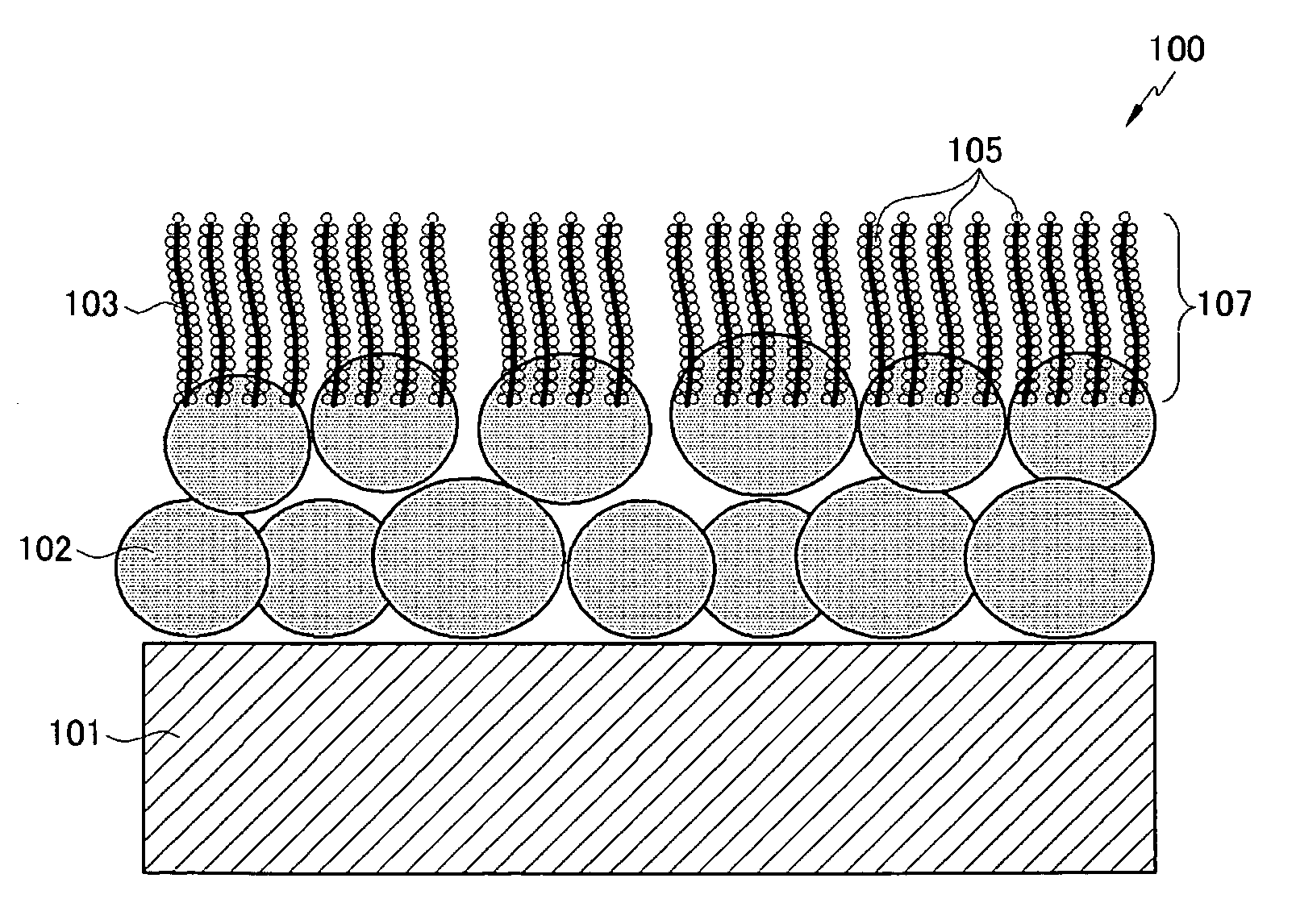
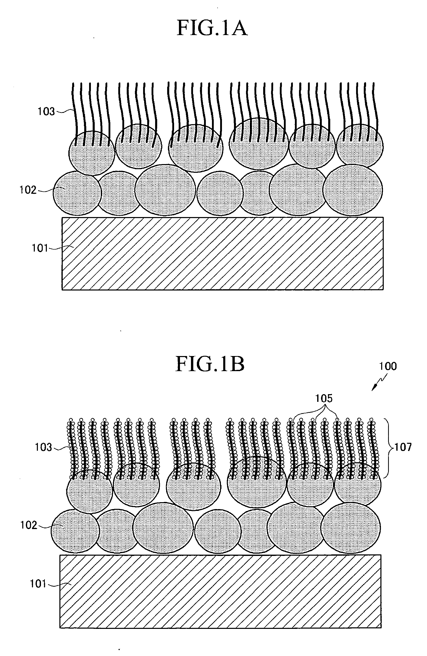
The present invention provides an improved electrode for a fuel cell with a large surface area and increased reaction efficiency. The electrode includes a microporous layer, nano-carbon, and a catalyst layer coated on the nano-carbon. The electrode substrate can function as both a backing layer and a dispersion layer. The invention also provides an MEA with the improved electrode and a fuel cell system including the electrodes. The method of preparing the electrode involves forming a microporous layer on a surface of an electrode substrate, introducing a first catalyst for synthesizing nano-carbon on the surface of the microporous layer, heating the first catalyst locally while providing a reactive gas including a carbon source gas to grow nano-carbon on the surface of the microporous layer, and coating a second catalyst on the nano-carbon to form a catalyst layer. The technical effects of the invention include increased surface area, improved reaction efficiency, and enhanced performance of fuel cells.

Problems solved by technology

However, platinum is a rare and expensive metal and thus is disadvantageous to use in a large amount.
However, supporting the platinum on the carbon can result in an increased thickness of the catalyst layer.
Furthermore, there are limits in the amount of platinum that can be stored on the catalyst layer.
Additionally, contact between this catalytic layer and the membrane may not be good, which may further deteriorate the fuel cell performance.

Method used


Image

  • Electrode for fuel cell, fuel cell comprising the same, and method for preparing the same
  • Electrode for fuel cell, fuel cell comprising the same, and method for preparing the same
  • Electrode for fuel cell, fuel cell comprising the same, and method for preparing the same

Examples


example 1

[0086] 3 g of carbon black, 0.2 g of polytetrafluoroethylene (PTFE), and 20 g of water as a solvent were mixed to prepare a composition. The composition was coated on a 200 μm-thick carbon cloth that was treated with PTFE to form a microporous layer. On the surface of the microporous layer, Fe as a first catalyst was dispersed in an amount of 0.02 mg / cm2 by sputtering. The Fe-dispersed carbon cloth was placed on a quartz boat of a reactor mounted with a microwave generator. Acetylene gas as a carbon source and argon gas were introduced into the reactor at room temperature for 20 minutes to grow carbon nanotubes having a diameter of about 10 nm and a length of about 2000 nm. The microwaves were controlled to irradiate the Fe selectively to heat it locally.

[0087] On the surface of the carbon nanotubes, Pt was deposited to fabricate an electrode. The electrode was dipped in 20 wt % of nitric acid for 2 hours to remove the remaining Fe. The fabricated electrode had a Pt content per uni...

example 2

[0089] A fuel cell was fabricated by the same method as in Example 1, except that Ni was used as a first catalyst.

example 3

[0090] A fuel cell was fabricated by the same method as in Example 1, except that carbon nanofibers were grown as the nano-carbon instead of the carbon nanotubes.


PUM

PropertyMeasurementUnit
thicknessaaaaaaaaaa
thicknessaaaaaaaaaa
thicknessaaaaaaaaaa

Abstract

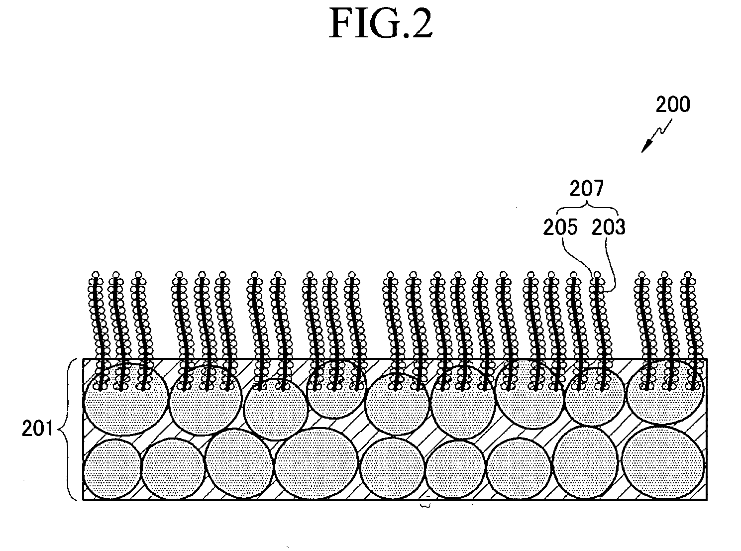
An electrode for a fuel cell of the present invention includes an electrode substrate, a microporous layer formed on the surface of the electrode substrate, and a nano-carbon layer formed on the surface of the microporous layer with a catalyst layer coated on the surface of the nano-carbon layer. Alternatively, an electrode for a fuel cell includes an electrode substrate in which carbon particles are dispersed, a nano-carbon layer on the electrode substrate, and a catalyst layer on the nano-carbon layer.

Description

CROSS REFERENCE TO RELATED APPLICATION [0001] This application claims priority to and the benefit of Korean Patent Application No. 10-2004-0097952 filed in the Korean Industrial Property Office on Nov. 26, 2004, the contents of which are incorporated hereinto by reference. FIELD OF THE INVENTION [0002] The present invention relates to an electrode for a fuel cell, a fuel cell including the same, and a method for preparing the same, and more particularly to an electrode which has a large surface area and thus improves electrochemical reaction, a fuel cell including the same, and a method for preparing the same. BACKGROUND OF THE INVENTION [0003] A fuel cell is a power generation system for producing electrical energy through an electrochemical redox reaction of an oxidant and a fuel such as hydrogen, or a hydrocarbon-based material such as methanol, ethanol, or natural gas. [0004] A fuel cell can be classified as a phosphoric acid type, a molten carbonate type, a solid oxide type, a ...

Claims


Application Information

Patent Timeline
Patent Type & Authority Applications(United States)
IPC IPC(8): H01M4/96H01M4/92H01M8/10H01M4/88B05D5/12
CPCB82Y30/00H01M4/8605H01M4/8825H01M4/921H01M4/926H01M2008/1095Y02E60/523Y02E60/50H01M4/86H01M4/88
Inventor KIM, HEE-TAKKWEON, HO-JINLEE, JONG-KI
Owner SAMSUNG SDI CO LTD
Learn More