Exposure apparatus, evaluation method and device fabrication method

Inactive Publication Date: 2006-06-08
CANON KK
View PDF4 Cites 19 Cited by
  • Summary
  • Abstract
  • Description
  • Claims
  • Application Information

AI Technical Summary

Benefits of technology

[0011] Accordingly, the present invention is directed to an exposure apparatus, an evaluation method, and a device fabri

Problems solved by technology

However, the lithography using the ultraviolet light has limitations when it comes to satisfying the rapidly promoted fine processing of a semiconductor device.
The debris causes contaminations, damages, and lowered reflectivity of optical elements, making uneven the light intensity and deteriorating the throughput.
On the other hands, while the EUV light source repeats emissions of the EUV light, the light intensity of the EUV light irradiated from the EUV light source deteriorates by damages and deterioration of the electrode, lowered reflectivity of mirrors caused by flying particles such as debris that is not removed.
However, Japanese Patent Application, Publication No. 2003-224053 directly (without through a condensing point) detects the EUV light irradiated from the EUV light source, and does not provide the detector in a cle

Method used


Image

  • Exposure apparatus, evaluation method and device fabrication method
  • Exposure apparatus, evaluation method and device fabrication method
  • Exposure apparatus, evaluation method and device fabrication method

Examples


Embodiment Construction

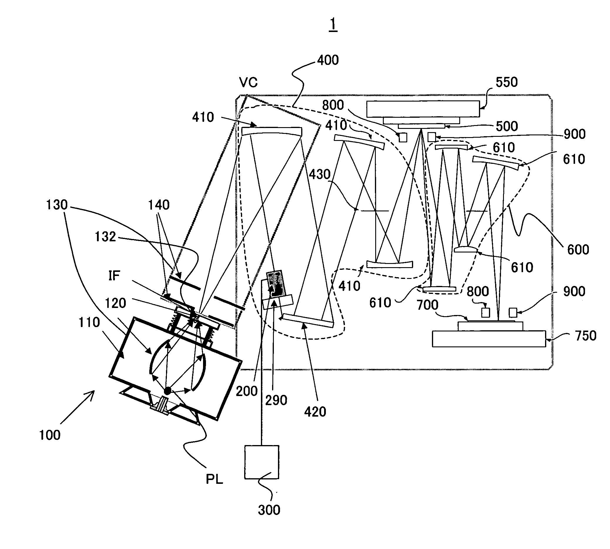
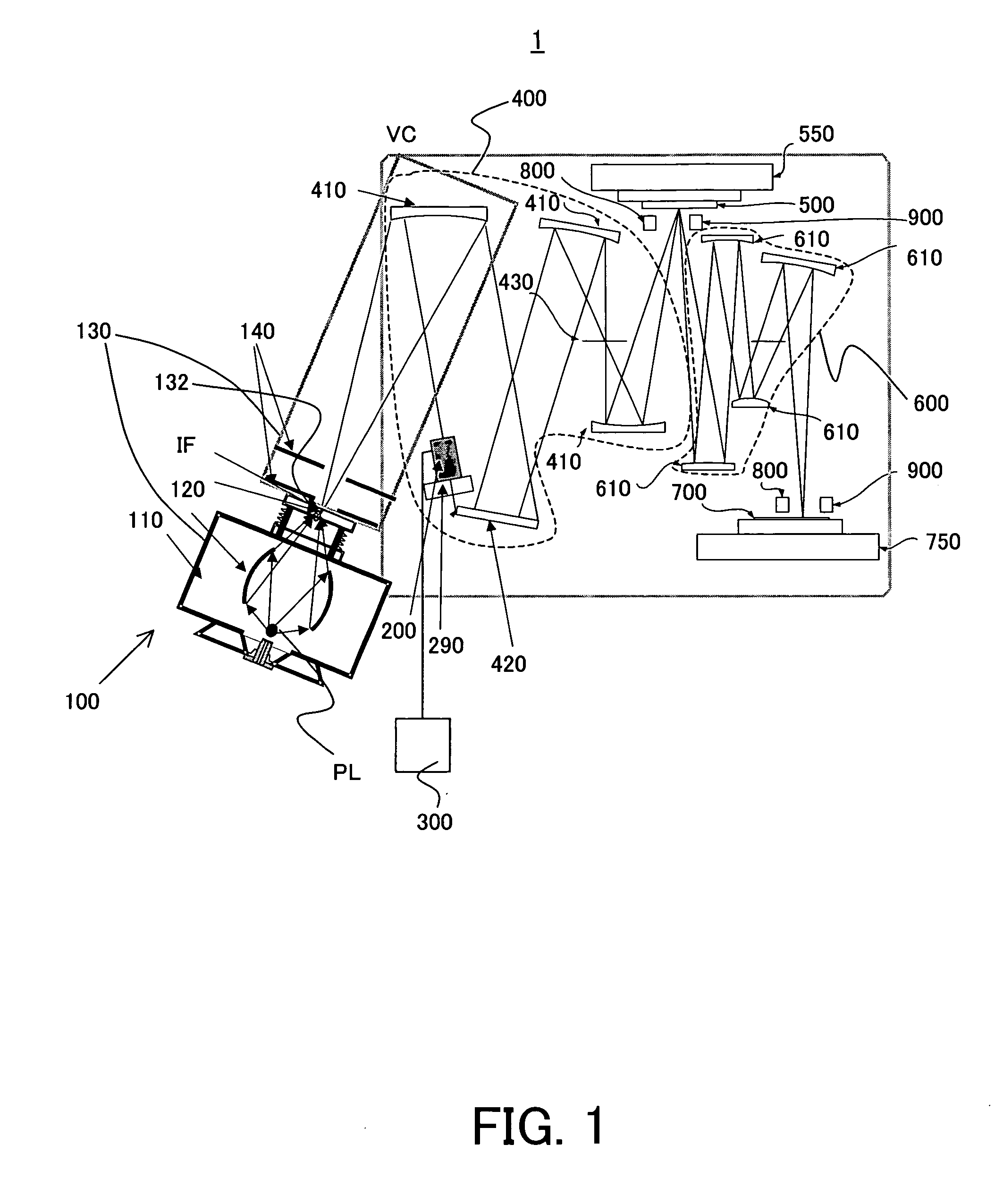
[0026] With reference to the accompanying drawings, a description will be given of an exposure apparatus as one aspect according to the present invention. In each figure, the same reference numeral denotes the same element. Therefore, duplicate descriptions will be omitted. Here, FIG. 1 is a schematic sectional view of the exposure apparatus 1 according to the present invention. In the exposure apparatus 1, an EUV light source part 100 side is an upstream side, and a mask 500 side is a downstream.

[0027] The exposure apparatus 1 of the present invention uses the EUV light (with a wavelength of, e.g., 13.4 nm) as illumination light for exposure, and exposes onto an object 700 a circuit pattern of a mask 500, for example, in a step-and-scan manner. Of course, the present invention is applicable to a step-and-repeat exposure apparatus (“stepper”). This exposure apparatus is suitable for a lithography process less than submicron or quarter micron, and the present embodiment uses the ste...


PUM


Abstract

An exposure apparatus for exposing a pattern of a mask onto an object, said exposure apparatus includes a light source part that includes a generating mechanism for generating a plasma, a condenser mirror for condensing a light radiated from the plasma, and a vacuum chamber for accommodating the generating mechanism and the condenser mirror, and has an opening that is provided at a position approximately corresponding to a position of a condensing point of the light condensed by the condenser mirror, an illumination optical system for illuminating the mask using the light from the light source part, a detector for detecting the light from the condensing point at an emission side of the condensing point, and an evaluation part for evaluating a life of the light source part based on a detected result by the detector.

Description

BACKGROUND OF THE INVENTION [0001] The present invention relates generally to an exposure apparatus, and more particularly to a life evaluation of a light source used in an exposure apparatus for exposing an object, such as a single crystal substrate of a semiconductor wafer etc. and a glass plate for a liquid crystal display (“LCD”). The present invention is suitable, for example, for an exposure apparatus that uses an extreme ultraviolet (“EUV”) light as a light source for exposure. [0002] Conventionally, the photolithography technology has employed a reduction projection exposure apparatus using a projection optical system to project a circuit pattern of a mask (reticle) onto a wafer, etc., in manufacturing fine semiconductor devices such as a semiconductor memory and a logic circuit. [0003] The minimum critical dimension to be transferred by the projection exposure apparatus or resolution is proportionate to a wavelength of light used for exposure, and inversely proportionate to...

Claims


Application Information

Patent Timeline
IPC IPC(8): G03B27/72
CPCB82Y10/00G03F7/70033G03F7/70525
Inventor ITO, JUNYAMAMOTO, TAKESHI
Owner CANON KK
Why Eureka
Try Eureka