Optical system

a technology of optical system and optical axis, applied in the field of optical system, can solve the problems of significant signal degradation, difficult to achieve rejection by simple baffling alone, and difficult to eliminate stray light sources, etc., to eliminate chromatic aberrations and simplify the design

Inactive Publication Date: 2006-06-08
NOVX SYST CANADA
View PDF2 Cites 11 Cited by
  • Summary
  • Abstract
  • Description
  • Claims
  • Application Information

AI Technical Summary

Benefits of technology

[0013] The size of the optical source and the magnification of the excitation beam path optics may be chosen in such a way as to produce a small focused spot in the center of the microplate well. This small spot, preferably less than 2 mm, causes the excitation beam to encounter only the zone within the center of the liquid meniscus having a near-axial surface normal. The axial surface normal of the central meniscus causes the angular bandwidth of the reflected excitation cone to be narrow, enabling rejection via apertures within the optical system.
[0014] A limiting aperture may be used to produce a low numerical aperture excitation beam. A low numerical aperture is desirable for two distinct reasons. Firstly, the low numerical aperture makes the excitation beam more amenable for absorption measurements, since the optical path through the well is made more columnar and less conical. Secondly, the lower angular bandwidth of the excitation beam incident on the well also serves to lower the angular bandwidth of the scattered excitation light cone produced by the meniscus. The limiting aperture also helps to eliminate multiple reflections caused by the lens collimating the excitation beam from the light source or fiber optic bundle.
[0015] The pick-off mirror is preferably chosen to have a diameter larger than that of the collimated excitation beam in order to reject a substantial amount of the low numerical aperture component of the scattered excitation light. The rejection of this component of the scattered excitation light via a mirrored surface removes a large fraction of the scattered excitation light from the optical system.
[0016] A shadow disc, comprising a thin opaque disc that preferentially absorbs light and reflects diffusely, may be placed immediately above the second focusing lens (the lens that focuses the emitted light) in order to stop scattered excitation light from reaching the focus. As a result of the aforementioned aspects that decrease the angular bandwidth of the scattered excitation light, the scattered excitation cone (the outer regions of which are produced by the meniscus) collimates to a diameter that can be less than that of the first lens (the lens that focuses the excitation beam and collimates the emitted light). By choosing a shadow disc that has a diameter that is slightly larger than the diameter of the collimated scattered excitation beam but less than that of the upper lens, the scattered excitation light is very effectively prohibited from directly scattering to the focus. Finally, since the scattered excitation beam is in many cases slowly converging after propagating through the first lens, a free propagation path between the first lens and the shadow disc can further increase the power of the collected emission light relative to the scattered excitation light.
[0021] The present invention also provides an embodiment of an optical system in which the aforementioned lenses are replaced with mirrors that simplify the design and eliminate chromatic aberrations. The low numerical aperture lens that had collimated the source and the reflecting mirror may be replaced with a single concave mirror that refocuses the excitation beam into the liquid containing vessel along an axis of the vessel. The upper focusing lens is replaced with an off-axis parabolic mirror. This mirror collimates the emitted light and reflects it in a direction normal to the well bottom. This mirror has a hole cut through it in order to pass the focusing excitation beam that is directed along the well axis. An aspheric lens may then be used to focus the light emitted from the liquid onto a detector, or a fiber bundle optically coupled to the detector. In front of the aspheric lens there may be included a shadow disc, which again serves to reject the narrow beam of collimated (or slowly converging) scattered excitation light. The aspheric lens may also be replaced with an on- or off-axis parabolic mirror.

Problems solved by technology

Despite the large number of patents pertaining to fluorometric instruments, little attention has been paid to the elimination of stray excitation light, which can cause significant signal degradation.
However, the dominant source of stray light in a microplate fluorometer is usually the liquid meniscus at the sample-air interface.
This source of stray light is particularly difficult to reject since the meniscus can vary in position (due to different sample volumes) and curvature (due to different surface properties).
Most importantly, a spatially extended beam impinging on the meniscus results in a wide angular bandwidth upon reflection, making it difficult to achieve rejection by simple baffling alone.
Unfortunately, the invention only succeeds in eliminating the collection of scattered excitation light for a very limited range of sample volumes and meniscus curvatures.

Method used


Image

  • Optical system
  • Optical system
  • Optical system

Examples


Embodiment Construction

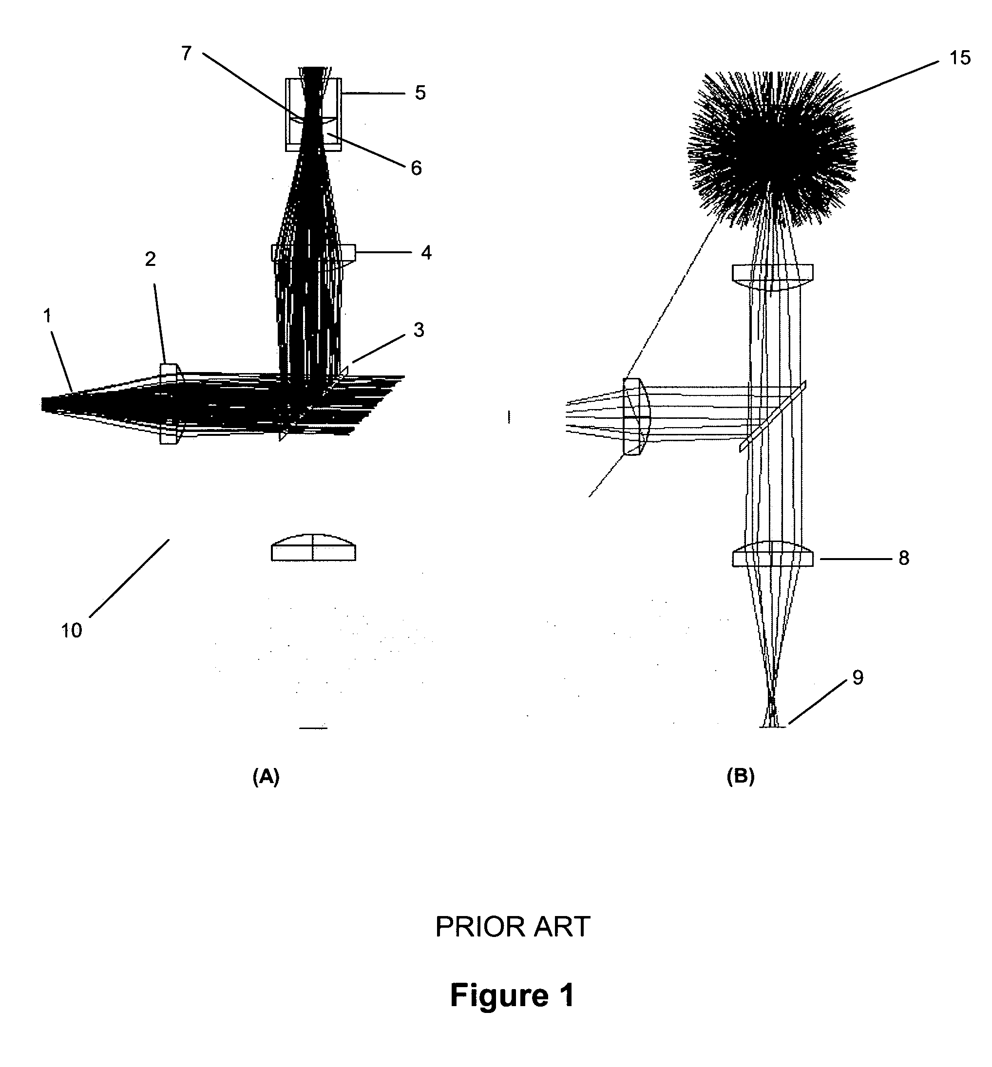
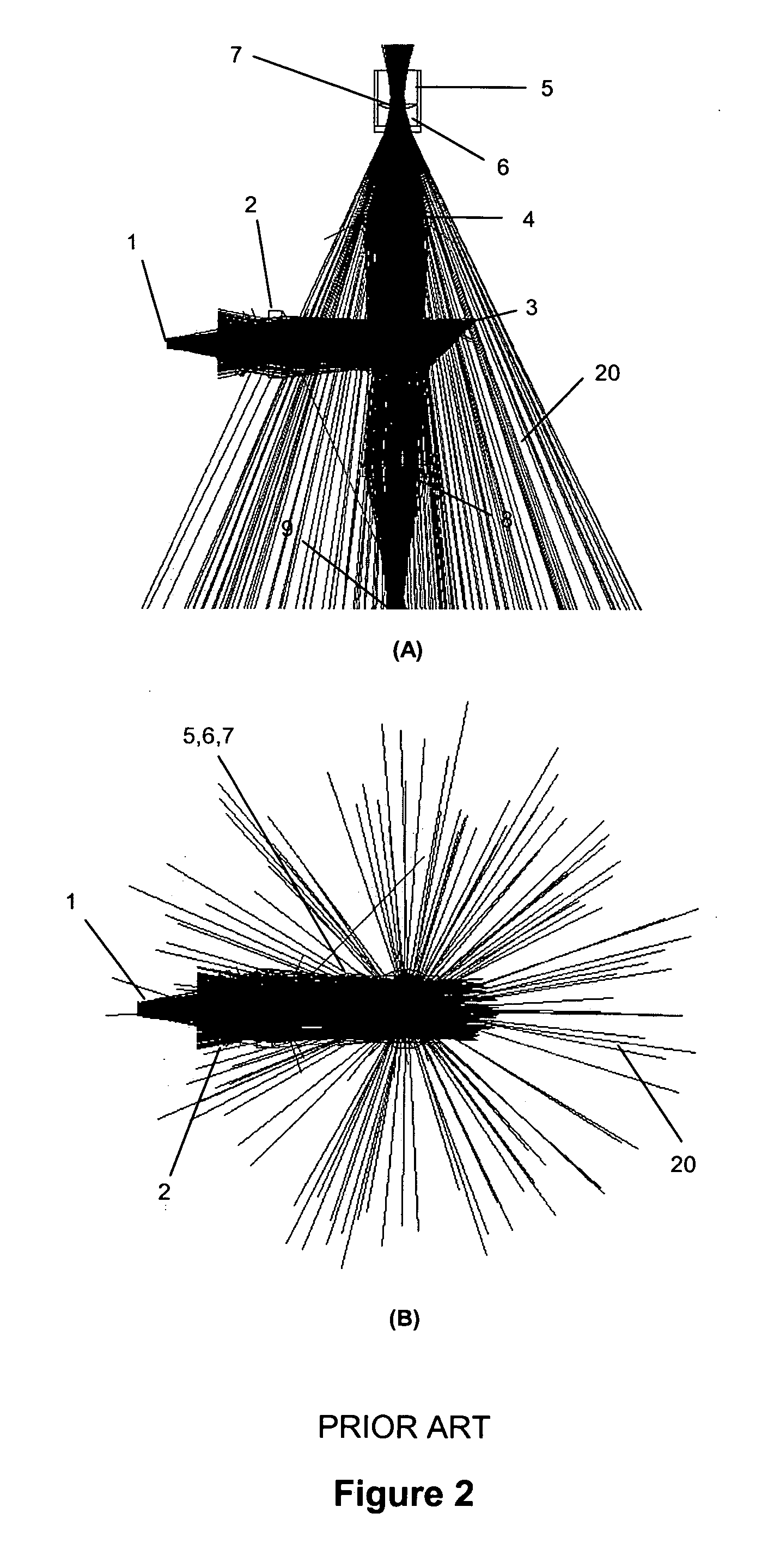
[0044] Referring to FIG. 1, there is a schematic of a conventional optical system 10 for measuring fluorescence from a microplate well or any other type of liquid sample containing vessel. In FIG. 1A, an optical source 1, usually either a filtered light source or a fiber optic bundle delivering filtered light, is collimated by lens 2 and reflected to the microplate well 5 by beamsplitter 3. A second lens 4 focuses the excitation light onto the microplate well, where it is focused into the fluorescent sample liquid 6 with meniscus 7. In FIG. 1B, the emitted light from the sample 15 is collimated by lens 4, propagates through beamsplitter 3 and is focused with lens 8 to a focal point 9. If no emission filter is used between beamsplitter 3 and lens 8, then focus 9 is usually coincident with the aperture of a fiber bundle that delivers the emitted light to a remote filtering and detection location. Otherwise, a detector is placed at the focus 9 and the optical power of the emitted light...


PUM

PropertyMeasurementUnit
sizeaaaaaaaaaa
core diameteraaaaaaaaaa

Abstract

An optical system is provided for achieving enhanced rejection of scattered excitation light and superior signal-to-noise performance when reading microplate wells. The optical system uses an axial configuration in which the excitation beam incident upon the sample propagates along the axis of the microplate well. Excitation light from a light source, such as a lamp or fiber optic bundle, is collimated into a beam using a lens. A reflective pick-off mirror is then used to reflect the collimated excitation beam upward along the well axis. A focusing lens, with a diameter exceeding the diameter of the collimated excitation beam, is used to focus the excitation beam in the well. The same broad lens is used to collimate the emitted fluorescent light, of which a large percentage propagates axially past the pick-off mirror towards a second focusing lens that focuses the emission beam onto the face of a fiber optic bundle. The emitted light is later filtered and detected using at a position that is optically shielded from the aforementioned optical system. The optical system is incorporated into a microplate reader or automated assay instrument in order to provide a compact assembly for sensitive fluorescence measurements either above or below the microplate. The optical system further enables the simultaneous measurement of absorbance and fluorescence in a compact optical configuration.

Description

FIELD OF THE INVENTION [0001] The present invention is related to an optical system for achieving enhanced rejection of scattered excitation light and superior signal-to-noise performance when reading microplate wells and more particularly the present invention relates to an optical system which enables the simultaneous measurement of absorbance and fluorescence in a compact optical configuration. BACKGROUND OF THE INVENTION [0002] Optical measurements are routinely used to detect and quantify the presence of species in chemical and biological samples. The most common forms of optical measurement are absorption, fluorescence, and luminescence. In absorbance measurements, the degree of attenuation caused by optical absorption is related to the concentration of the species of interest. Fluorescence measurements involve exciting the sample via short-wavelength optical radiation and measuring the optical power of longer-wavelength fluorescence. Luminescence measurements rely on the meas...

Claims


Application Information

Patent Timeline
Patent Type & Authority Applications(United States)
IPC IPC(8): G01N21/64
CPCG01N21/6452
Inventor LEONARD, STEPHEN W.XU, MING GANG
Owner NOVX SYST CANADA
Why Eureka
Try Eureka