
Apparatus for driving inductive load

Active Publication Date: 2006-06-08
DENSO CORP
View PDF8 Cites 11 Cited by
  • Summary
  • Abstract
  • Description
  • Claims
  • Application Information

AI Technical Summary

Benefits of technology

[0008] It is therefore an object of the present invention to provide an inductive load driving apparatus that is simple in configuration, yet reliable in communicating a thermally abnormal state of the apparatus to an external controller.
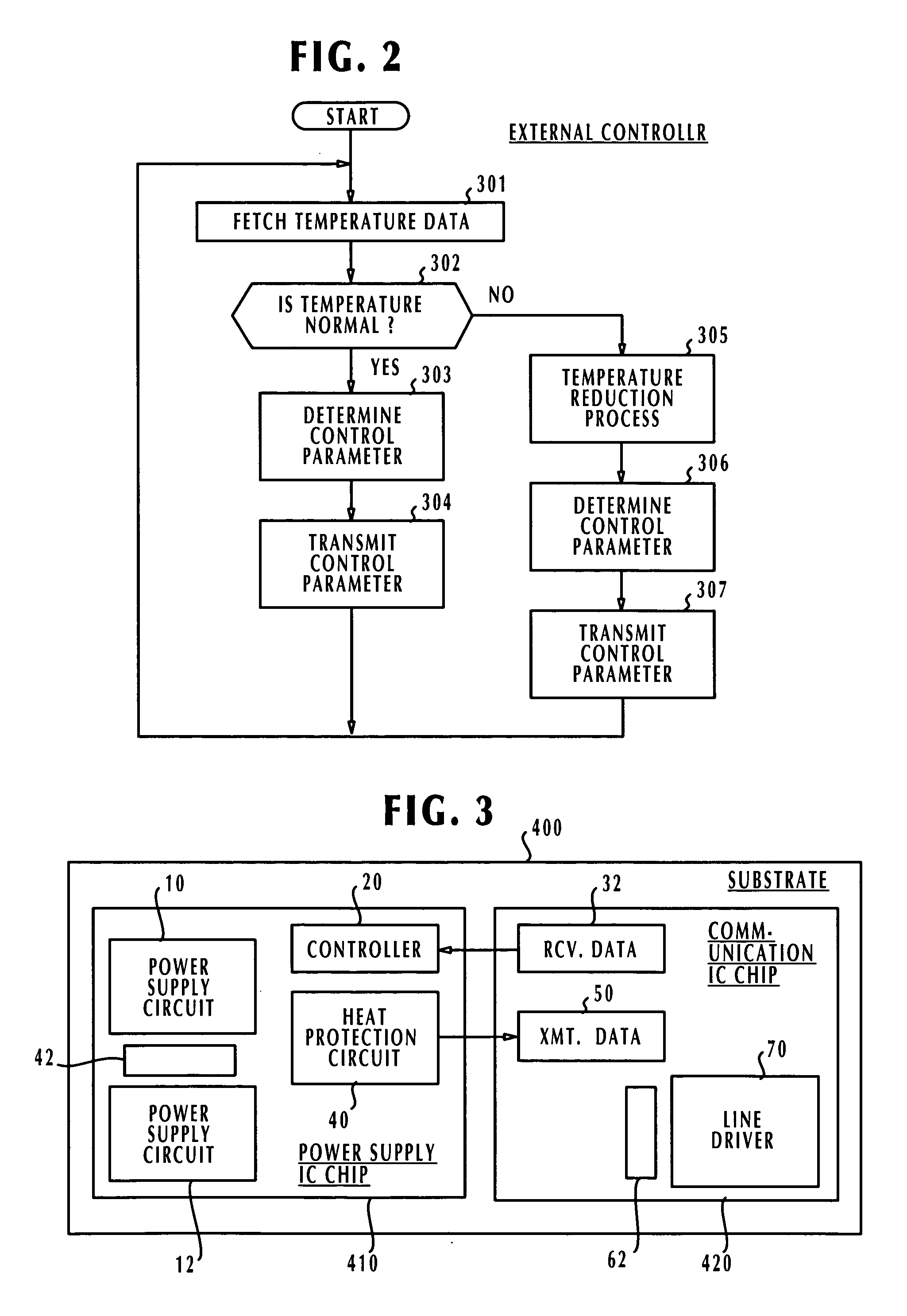
[0011] In order to further reduce the thermal interference between the power supply circuits and the heat protection circuit of the line driver, it is preferable that the second heat protection circuit is formed in an area adjacent to the line driver but remote from the power supply circuits, so that the line driver and the power supply circuits are located in positions not oppositely facing each other.
[0014] Preferably, the power supply circuits, the line driver, and the first and second heat protection circuits are formed on a same integrated circuit chip, and the power supply circuits and the line driver are separated from each other. With this arrangement, the operating thermal characteristics of the first heat protection circuit faithfully reflect the actual temperature of the power supply circuits and likewise, the operating thermal characteristics of the second heat protection circuit faithfully reflect the actual temperature of the line driver. As a result, the threshold temperature difference between the two heat protection circuits can be easily maintained and their degree of precision can be improved.
[0015] Preferably, the power supply circuits are constructed of semiconductor devices that are different in type from the semiconductor devices of which the line driver is constructed. The use of different semiconductor types serves to enhance the effect of the threshold temperature difference between the two heat protection circuits.
[0017] Furthermore, it is preferable that the heat sink is cooled off by the liquid that is used to cool the inductive load or an actuator that operates with it. Cooling the heat sink with liquid serves to improve the heat dissipation characteristic of the heat sink and allows communication of abnormal conditions to the external controller, such as abnormally high ambient temperature and abnormal condition of the cooling system.

Problems solved by technology

This arrangement results in a complex configuration.
Further, if thermal coupling should exist between these power supply circuits, their heat protection circuits are likely to operate differently from each other, causing an error signal to be transmitted to the external controller.

Method used


Image

  • Apparatus for driving inductive load
  • Apparatus for driving inductive load
  • Apparatus for driving inductive load

Examples


Embodiment Construction

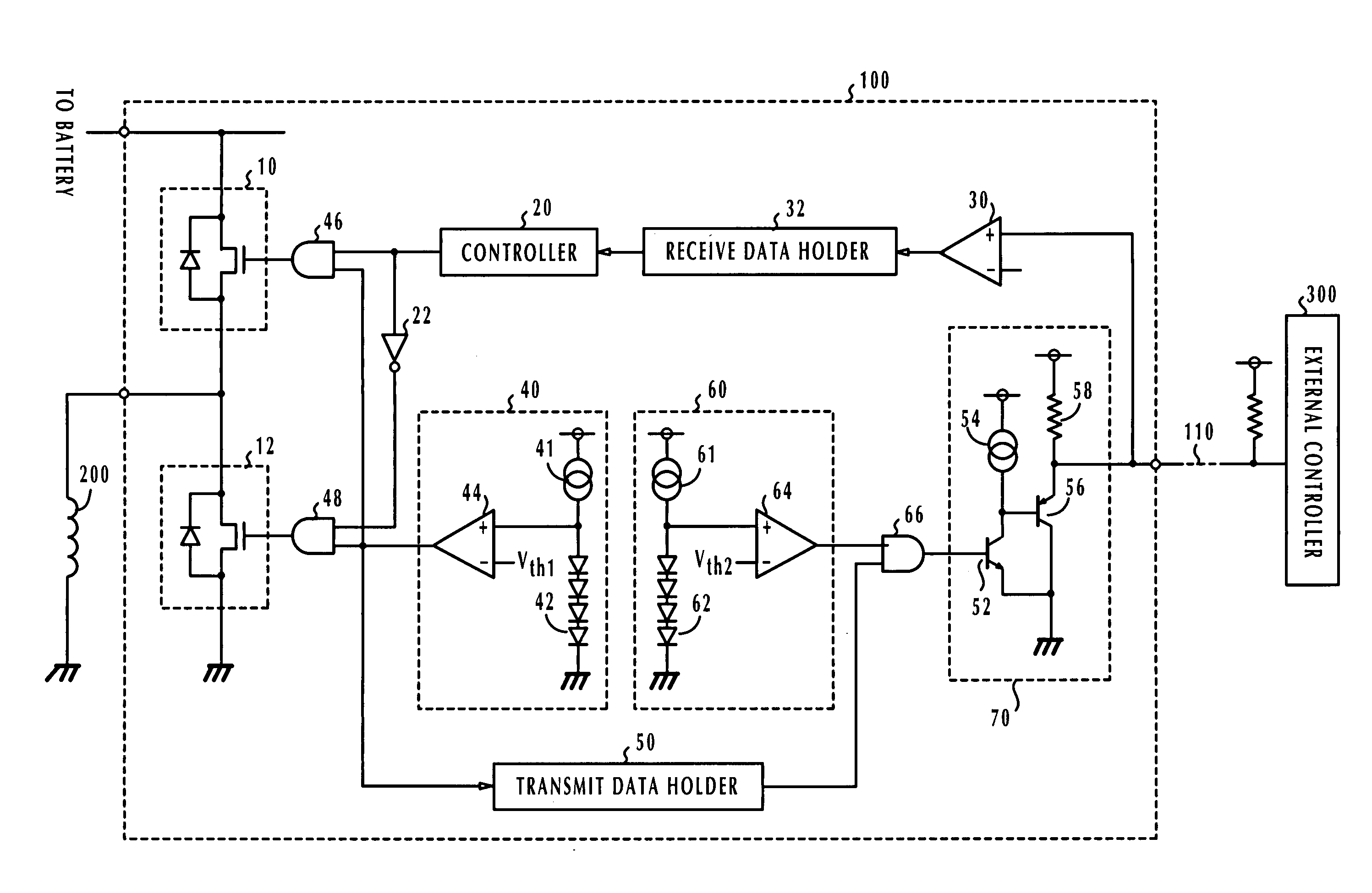
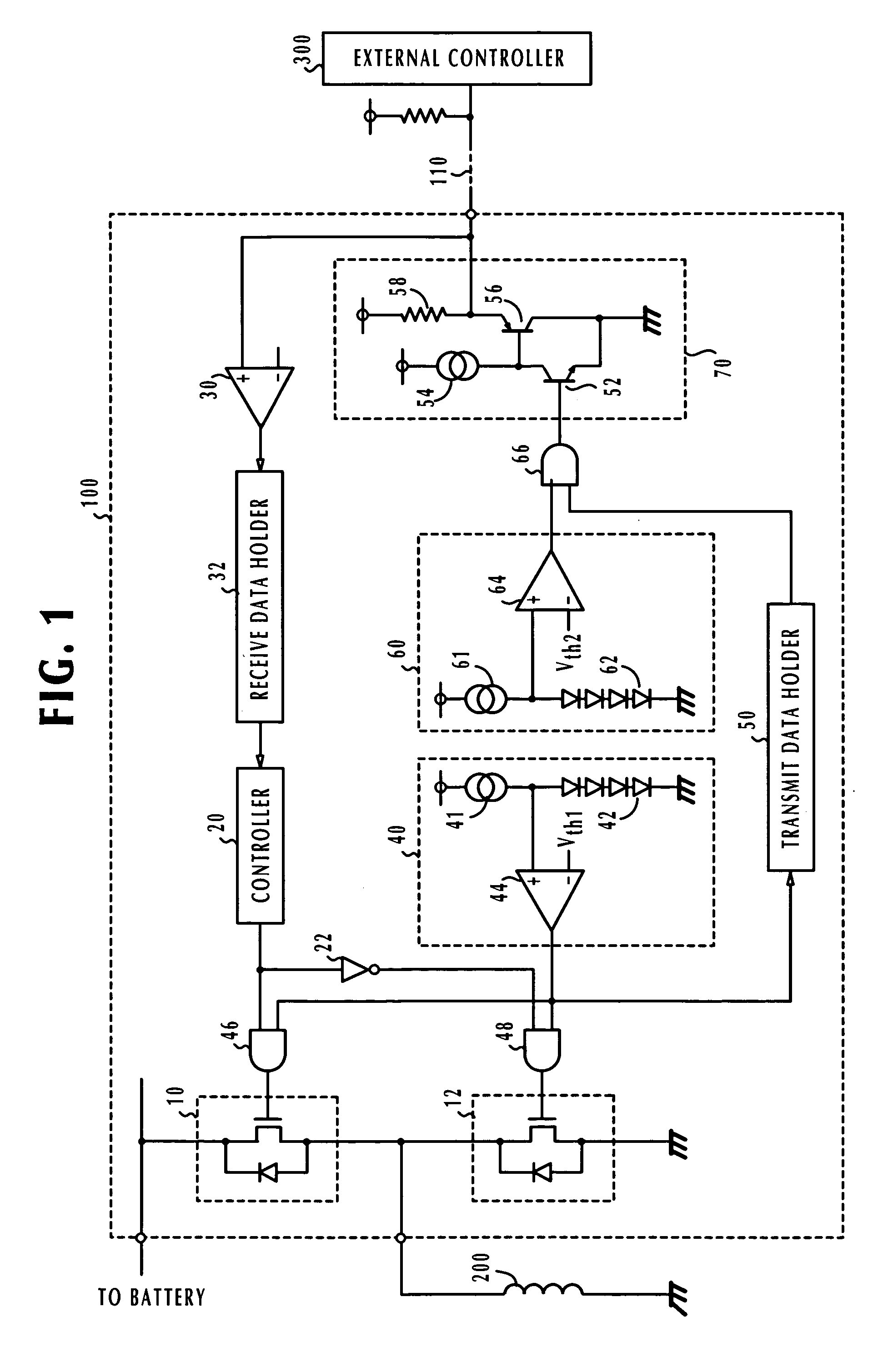
[0031] In FIG. 1, there is shown an apparatus 100 constructed according to a preferred embodiment of the present invention for driving an inductive load 200. Apparatus 100, which is usually mounted on a motor vehicle, is connected to an external controller 300 via a communication link 110 to receive control data through a line receiver 30 and transmit control data through a line driver 70. The data transmitted from the external controller 300 is detected by the line receiver 30 and stored in a receive data holder 32 and supplied to a control circuit 20.

[0032] Connected in series between a battery (not shown) and ground is a pair of power supply circuits 10, 12, each of which is a parallel circuit of a field-effect transistor (or power MOSFET) and a diode, with the circuit node between them being connected to the inductive load 200. Power supply circuits 10, 12 operate with a logic circuit that is formed with AND gates 46, 48 and inverter 22 to perform complementary ON-OFF power con...


PUM


Abstract

An apparatus is disclosed that drives an inductive load according to a control signal from an external controller transmits temperature data to it for indicating a condition of the inductive load through a line driver. The external controller regenerates the control signal according to the temperature data. According to the control signal, the apparatus operates a pair of power supply circuits to complementarily supply power to the load. Thermal conditions of the power supply circuits and the line driver are monitored for detecting an overheat condition. The transmission of temperature data to the external controller is enabled as long as no overheat condition is detected in both of the power supply circuits and line driver. If an overheat condition is detected in at least one of the power supply circuits and line driver, heat protection is performed and the overheat condition is communicated to the external controller.

Description

CROSS-REFERENCE TO RELATED APPLICATION [0001] This application is based on Japanese Patent Applications No. 2004-353732, filed Dec. 7, 2004, which is incorporated herein by reference. BACKGROUND OF THE INVENTION [0002] 1. Field of the Invention [0003] The present invention relates to an apparatus for driving an inductive load according to an instruction from an external controller. [0004] 2. Description of the Related Art [0005] As disclosed in Japanese Patent No. 3482948, it is known that, in an apparatus that drives an inductive load such as solenoid, a heat protection arrangement is provided to prevent its power supply circuit from being overheated when the operation of the load deviates from a normal condition. In the disclosed apparatus, the power supply circuit consists of a number of output stages that are thermally decoupled from each other and a heat protection circuit is provided for each output stage. [0006] According to another technique as disclosed in Japanese Patent P...

Claims


Application Information

Patent Timeline
IPC IPC(8): H02H5/04H02M7/48
CPCH03K17/0822
Inventor ASADA, TADATOSHI
Owner DENSO CORP
Learn More