
Patterned substrate, electro-optical device, patterned substrate manufacturing method and electric-optical device manufacturing method

a technology of electrooptical devices and patterned substrates, which is applied in the direction of discharge tubes luminescnet screens, instruments, transportation and packaging, etc., can solve the problems of shape variation among the patterns within the patterned substrates, unwanted variation in etc., to improve the uniform shape of the pattern formed by drying liquid droplets, improve the uniformity of the shape of the pattern, and improve the uniformity of the pattern shape

Inactive Publication Date: 2006-06-08
SEIKO EPSON CORP
View PDF4 Cites 3 Cited by
  • Summary
  • Abstract
  • Description
  • Claims
  • Application Information

AI Technical Summary

Benefits of technology

[0009] An advantage of the invention is to provide a patterned substrate, an electro-optical device, a patterned substrate manufacturing method, and an electric-optical device manufacturing method in which the uniformity of the shape of a pattern formed by drying liquid droplets is improved.
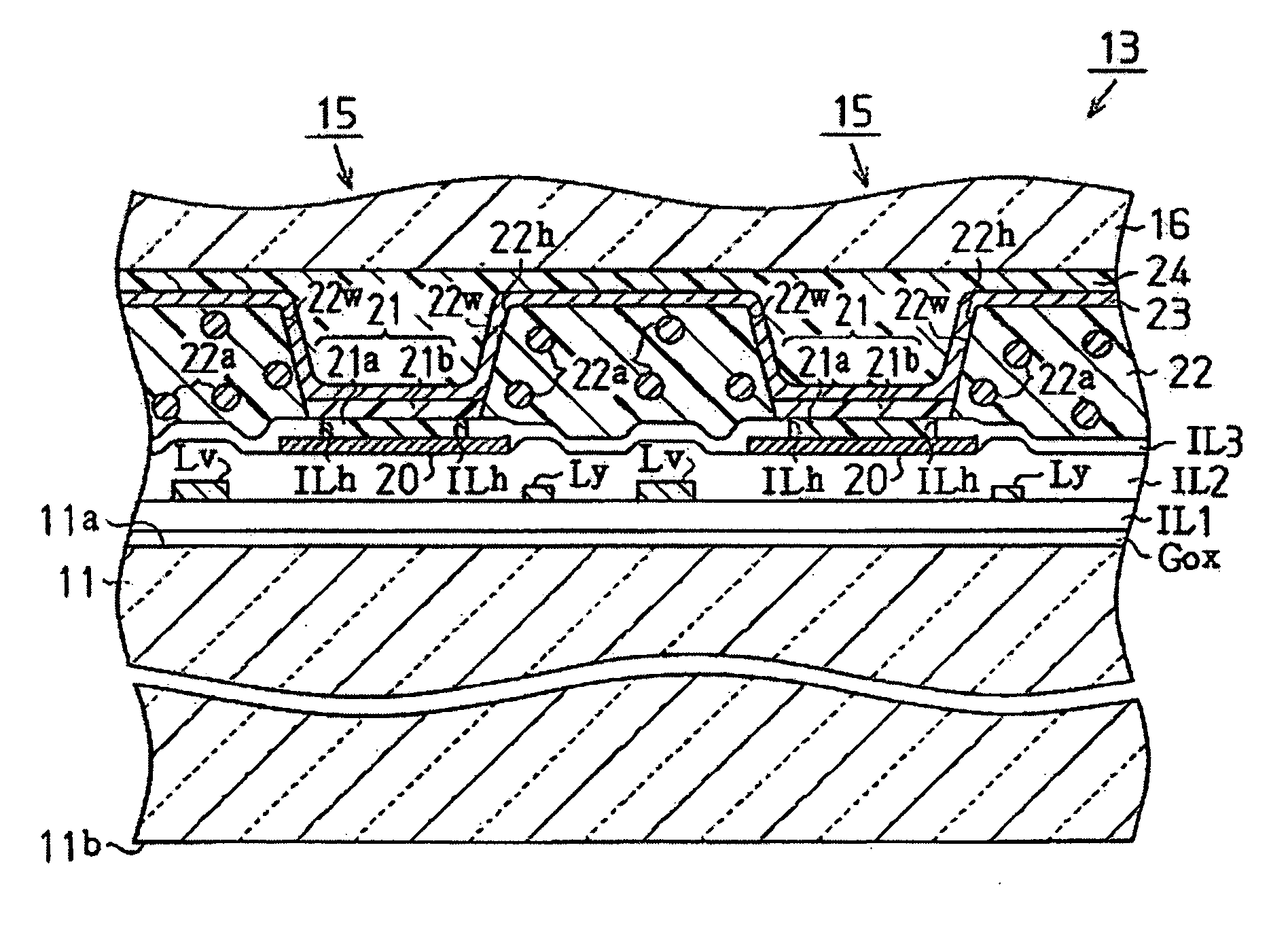
[0010] A patterned substrate in accordance with a first aspect of the invention is a patterned substrate having an element forming surface, a plurality of patterns formed on the element forming surface by drying liquid droplets containing a pattern forming material, wherein a photothermal conversion part configured to convert infrared light into heat is provided on an outside perimeter of each of a plurality of pattern forming regions, each pattern forming region being formed to correspond to one of the patterns.
[0011] With a patterned substrate in accordance with the first aspect of the invention, since a photothermal conversion part is provided on the outside perimeter of each pattern forming region, photothermal conversion parts are concentrated (provided more densely) in the places where the pattern forming regions are formed more densely. Consequently, due to the formation of the photothermal conversion parts, the drying conditions of each droplet can be made more uniform and the uniformity of the shapes of the patterns can be improved.
[0012] It is preferable that the photothermal conversion parts contain an infrared absorbing pigment. With this patterned substrate, the heat generated by the infrared absorbing pigment contained in the photothermal conversion parts enables the drying conditions of the liquid droplets to be made uniform and the uniformity of the shapes of the patterns to be improved.
[0013] It is preferable that the photothermal conversion parts be provided with partitioning walls configured to hold the liquid droplets in the pattern forming regions. With this patterned substrate, since the liquid droplets are held by the partitioning walls of the photothermal conversion parts, the liquid droplets can be dried by the photothermal conversion parts until the pattern forming material of the held liquid droplets forms the patterns. Thus, the drying conditions of the liquid droplets can be made more uniform and the uniformity of the shapes of the patterns can be improved.
[0014] It is preferable that the pattern forming material be a light emitting element forming material and that the patterns be light emitting elements. With this patterned substrate, the drying conditions of the light element forming material can be made uniform and the uniformity of the shape of the light emitting elements can be improved.

Problems solved by technology

Consequently, if the drying conditions vary, unwanted variation will occur in the pattern shape (e.g., the film thickness profile of the organic EL layers) among the patterns within an organic EL element substrate (patterned substrate).
Thus, the problem of shape variation among the patterns within the patterned substrate still occurs.

Method used


Image

  • Patterned substrate, electro-optical device, patterned substrate manufacturing method and electric-optical device manufacturing method
  • Patterned substrate, electro-optical device, patterned substrate manufacturing method and electric-optical device manufacturing method
  • Patterned substrate, electro-optical device, patterned substrate manufacturing method and electric-optical device manufacturing method

Examples


Embodiment Construction

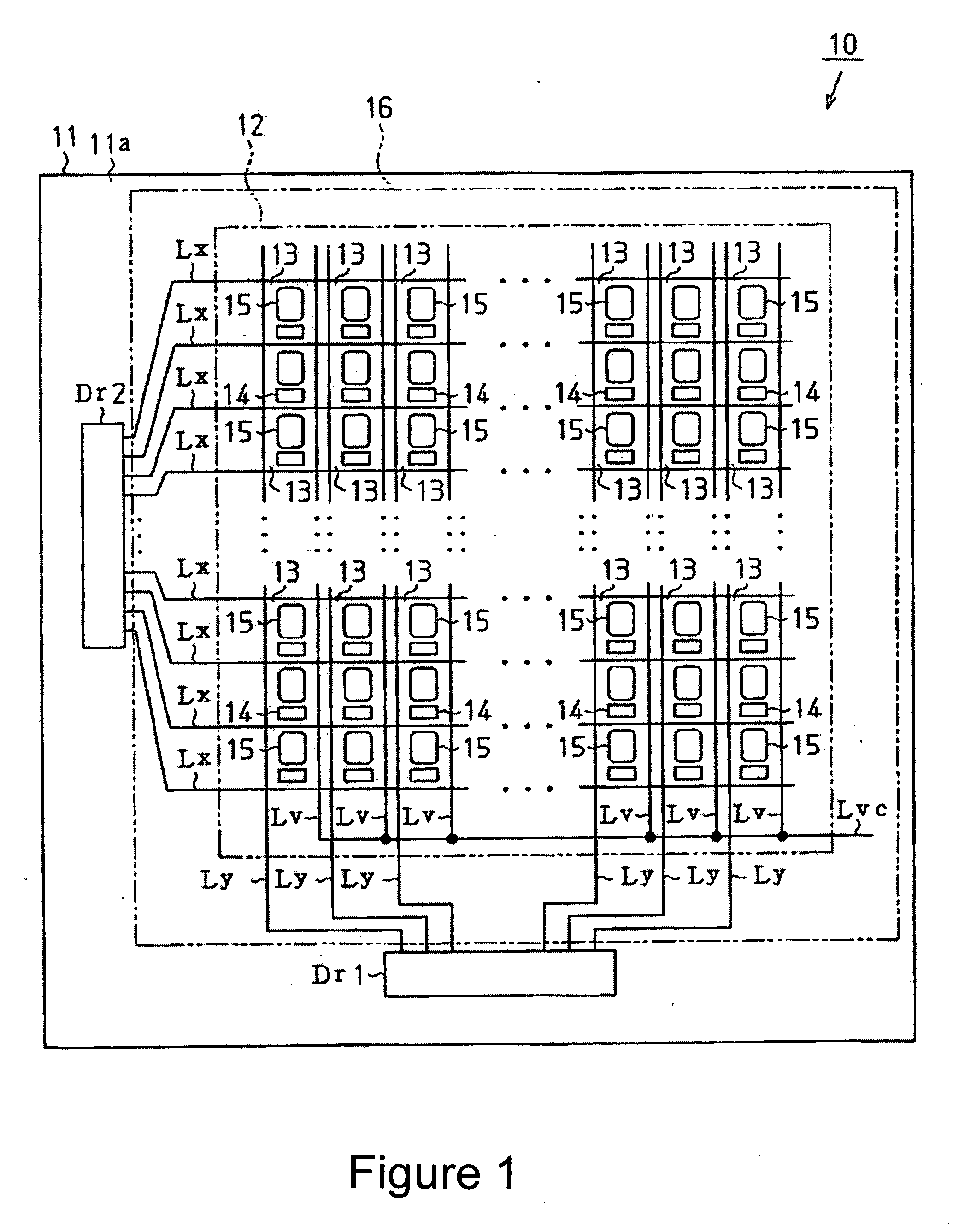
[0047] An embodiment of the invention will now be described with reference to FIGS. 1 to 9. FIG. 1 is a schematic plan view of an organic electroluminescent display (organic EL display) which is an example of an electro-optical device.

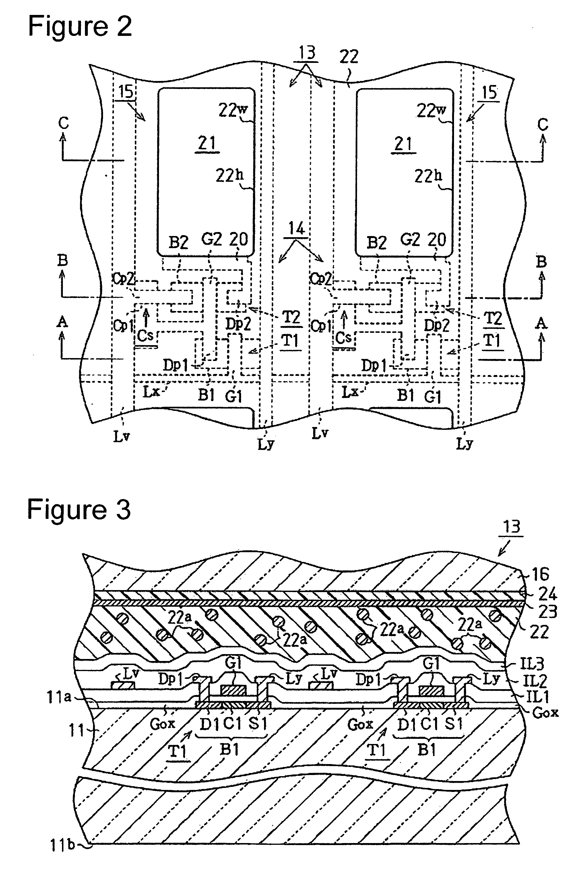
[0048] As shown in FIG. 1, the organic EL display 10 has a transparent substrate 11 as an example of a patterned substrate and a light emitting element-encompassing substrate. The transparent substrate 11 is a non-alkaline glass substrate that is formed into a rectangular shape and has an element forming region 12 formed on the surface thereof (element forming surface 11a). A plurality of data lines Ly that run in the vertical direction (column direction) are formed with a prescribed spacing there-between in the element forming region 12. Each data line Ly is electrically connected to a data drive circuit Dr1 arranged toward the bottom of the transparent substrate 11. The data drive circuit Dr1 is configured to generate a data signal based on display ...


PUM

PropertyMeasurementUnit
wavelengthsaaaaaaaaaa
perimeteraaaaaaaaaa
transparentaaaaaaaaaa

Abstract

A patterned substrate includes a plurality of patterns formed by drying liquid droplets containing a pattern forming material and a photothermal conversion part configured to convert infrared light into heat provided on an outside perimeter of each of a plurality of pattern forming regions, each pattern forming region being formed to correspond to each of the patterns.

Description

BACKGROUND [0001] 1. Technical Field [0002] The invention relates to a patterned substrate, an electro-optical device, a patterned substrate manufacturing method, and an electric-optical device manufacturing method. [0003] 2. Related Art [0004] One known example of a conventional display equipped with light emitting elements is the organic electroluminescent display (organic EL display), which is an electro-optical device equipped with organic electroluminescent elements (organic EL elements). The manufacturing methods for organic EL elements are generally classified according to the material from which the light emitting layer is made. More specifically, when the light emitting layer is made of a low molecular organic material, the light emitting layer is formed by vapor deposition of the low molecular organic material, i.e., a vapor phase process is used. Meanwhile, when a high molecular organic material is used as the material for making the light emitting layer, the light emitti...

Claims


Application Information

Patent Timeline
Patent Type & Authority Applications(United States)
IPC IPC(8): B41M5/00H01L51/52H01L51/56H10K99/00
CPCH01L27/3211H01L27/322Y10T428/24802H01L51/56H01L51/0005H10K59/35H10K59/38H10K71/135H10K71/421H05B33/22H05B33/10H10K71/00
Inventor TOYODA, NAOYUKI
Owner SEIKO EPSON CORP
Learn More