Template generating method and apparatus of the same, pattern detecting method, position detecting method and apparatus of the same, exposure apparatus and method of the same, device manufacturing method and template generating program

Inactive Publication Date: 2006-06-15
NIKON CORP
View PDF17 Cites 72 Cited by
  • Summary
  • Abstract
  • Description
  • Claims
  • Application Information

AI Technical Summary

Benefits of technology

[0042] According to the present invention, there are provided a template generating method, template generating apparatus, and template generating program for generating a template not changing due to deformation of the of the image of the mark (photoelectric conversion signal) due to differences in optical conditions, process conditions, etc., in other words, a template handling such deformation. Further, it is possible to provide a template generating method, template generating apparatus, and template generating program enabling such a template to be easily generated from various input sources. Further, it is possible to provide a pattern detecting method able to suitably detect a pattern for detection set by any method while absorbing deformation of the pattern (mark) using a template not changing due to deformation of the of the image of the mark (photoelectric conversion signal) due to differences in optical conditions, process conditions, etc.
[0043] Further, it is possible to provide a position detecting method and position detecting apparatus enabling a pattern for detection set by any method to be detected using a template not changing due to defor

Problems solved by technology

For example, a mark may be damaged while going through a plurality of exposure processes making it difficult to maintain the shape as designed or the shape at the time of initial formation.
Further, the thickness of the resist film coated over the mark may cause the shape of the mark as observed to change.
However, the method of performing edge extraction, binarization, or other pre-processing is complicated in processing and has insufficient points in terms of the processing performance such as the difficulty in detection of the edge positions.
Further, the problem arises of the difficulty in determining a suitable template.
This is therefore not an effective countermeasure.
However, the method of configuring the system or mark so as to prevent the mark image from changing in shape is limited technologically wise and increases the cost.
Further, if trying to realize this, in many cases the problem of imposing limitations on the mark structure ends up arising.
This therefore cannot be said to be an effective method.
However, the method of adaptively generating templates and using them for matching has the prob

Method used


Image

  • Template generating method and apparatus of the same, pattern detecting method, position detecting method and apparatus of the same, exposure apparatus and method of the same, device manufacturing method and template generating program
  • Template generating method and apparatus of the same, pattern detecting method, position detecting method and apparatus of the same, exposure apparatus and method of the same, device manufacturing method and template generating program
  • Template generating method and apparatus of the same, pattern detecting method, position detecting method and apparatus of the same, exposure apparatus and method of the same, device manufacturing method and template generating program

Examples


Example

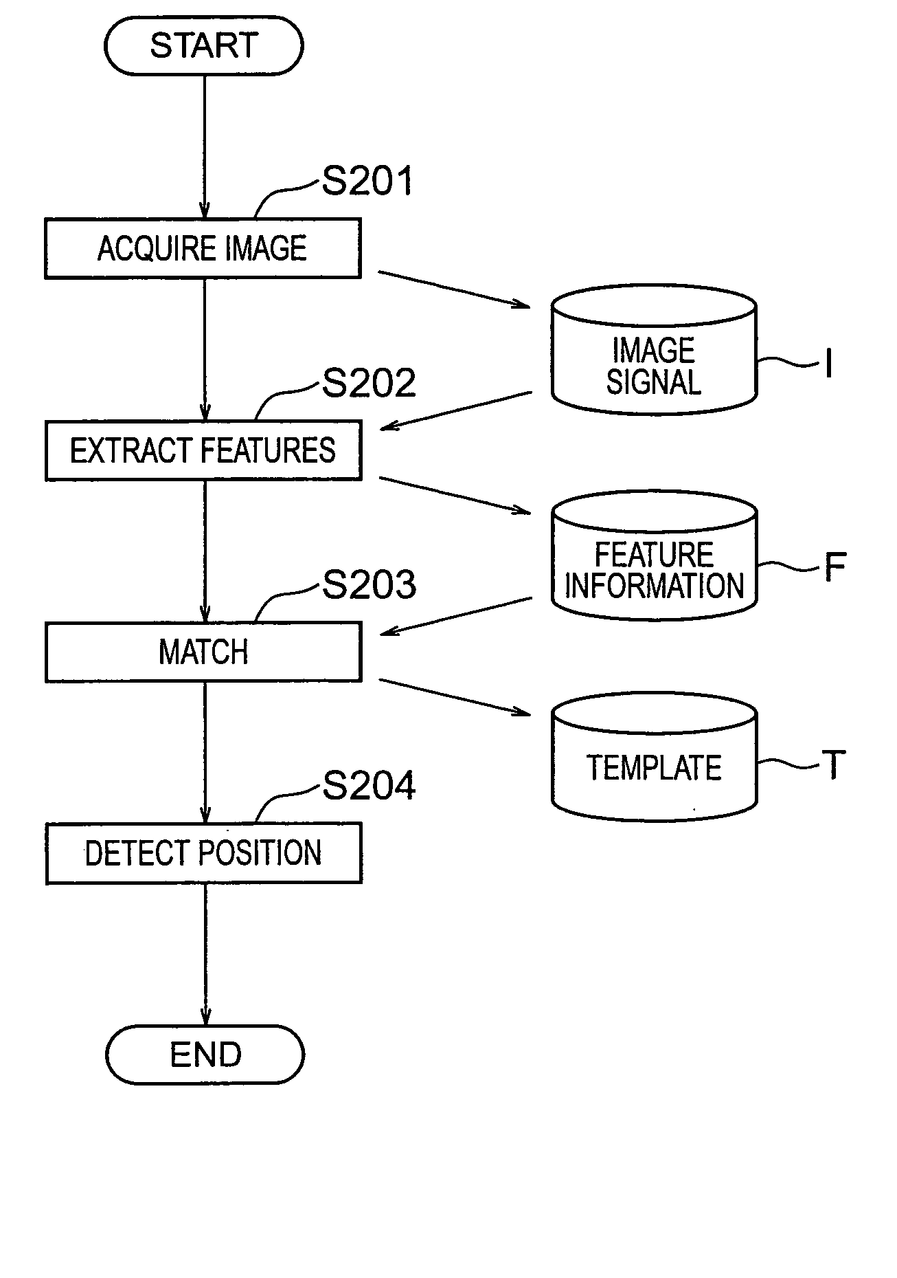
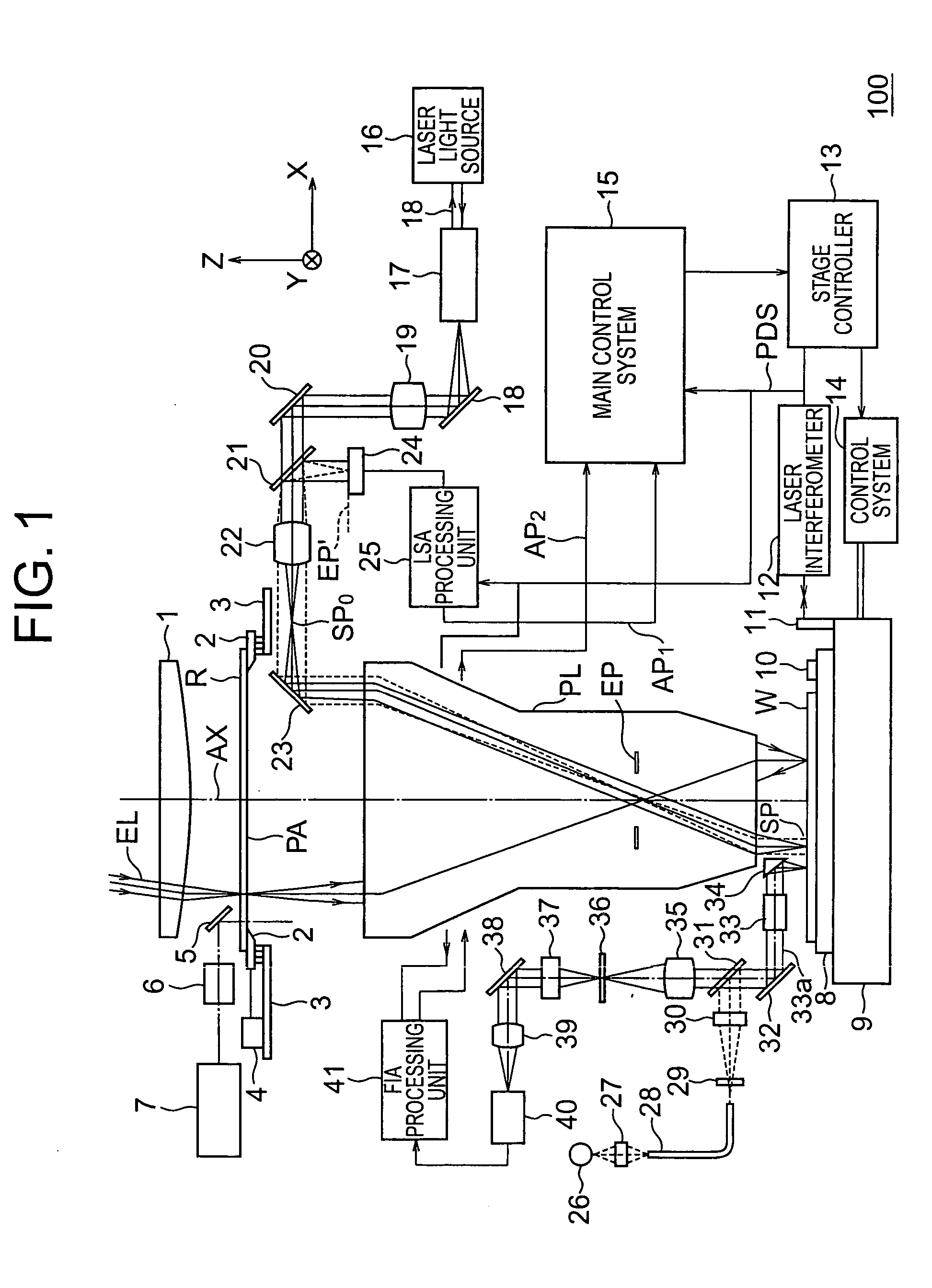
[0070] A first embodiment of the present invention will be explained with reference to FIG. 1 to FIG. 14B. In the first embodiment, the explanation will be given of using a feature not changing even if the image of a mark (photoelectric conversion signal) deforms due to a difference in the optical conditions or process conditions for generation of a template, pattern detection using that template, position detection based on the pattern detection results, and exposure based on the position detection results. Specifically, in the present embodiment, the explanation will be given of an exposure apparatus having an off-axis type alignment optical system for detecting an alignment mark of a wafer by image processing using a template generated by the template generating method according to the present invention and a pattern detecting method and position detecting method according to the present invention.

[0071] First, the configuration of the exposure apparatus will be explained with r...

Example

[0131] A second embodiment of the present invention will be explained with reference to FIG. 15 to FIG. 23. In the second embodiment, the method of generating a pattern model when forming a pattern on a wafer for pattern data input from various input sources, using an optical image deformation simulator to generate a pattern image (virtual model) obtained when obtaining an image of that pattern model, and using this to generate a template corresponding to deformation of the pattern will be explained. Further, the pattern detection using that template, the position detection based on the results of pattern detection, and the exposure based on the results of position detection will be explained.

[0132] Specifically, in the present embodiment as well, an exposure apparatus having an off-axis type alignment optical system for detecting an alignment mark (mark pattern) or circuit pattern formed on a wafer by image processing and using a template generated by the template generating metho...


PUM


Abstract

A method enabling easy generation of a template handling pattern deformation due to optical conditions or process conditions and suitably detecting pattern position is disclosed. A first method extracts a feature component, that is, symmetry, not affected by optical conditions etc. from the pattern image information and uses it as a template. At the time of pattern detection, image information is projected into a symmetry feature space and matching performed in the feature space to detect a pattern. Suitable template matching can be performed with being affected by pattern deformation. A second method generates a model of a pattern from input pattern data, calculates a plurality of pattern images (virtual models) obtained by imaging of the model for each imaging condition using an image deformation simulator, and determines a template considering their average or correlation.

Description

BACKGROUND OF THE INVENTION [0001] 1. Field of the Invention [0002] The present invention relates to a template generating method, apparatus, and program suitable for application for positioning a wafer, reticle, etc. in a lithography process when producing for example a semiconductor element or other electronic device, a pattern detecting method detecting a mark or other pattern using a generated template, a position detecting method and apparatus for detecting a position of a wafer etc. based on a detected mark etc., an exposure method and apparatus for exposure based on the detected position of a wafer etc., and a device manufacturing method for manufacturing an electronic device by performing such exposure. [0003] 2. Description of the Related Art [0004] In the process for manufacture of for example a semiconductor element, liquid crystal display element, plasma display element, thin film magnetic head, or other electronic device (below, referred to all together as an “electroni...

Claims


Application Information

Patent Timeline
IPC IPC(8): G06K9/00G01B11/00G03F7/20G03F9/00H01L21/027
CPCG03F9/7076G03F9/7088G03F9/7092
Inventor KOKUMAI, YUJI
Owner NIKON CORP
Why Eureka
Try Eureka