Optical fiber illuminator, method of fabricating the optical fiber illuminator, and optical recording head and optical recording and reading apparatus having the optical fiber illuminator

a technology of optical fiber and illuminator, which is applied in the field of optical fiber illuminator, method of fabricating optical fiber illuminator, and optical recording head and optical recording and reading apparatus having optical fiber illuminator, etc., can solve the problems of low optical transmission efficiency of optical waveguide into aperture probe, limiting recording density, and integrating optical waveguid

Inactive Publication Date: 2006-06-15
ELECTRONICS & TELECOMM RES INST
View PDF8 Cites 14 Cited by
  • Summary
  • Abstract
  • Description
  • Claims
  • Application Information

AI Technical Summary

Benefits of technology

[0022] Still another aspect of the present invention provides an optical recording head having an optical fiber illuminator, the optical recording head including: the optical fiber illuminator described above; a support frame supporting the optical fiber illuminator and having an opening to pass light incident through the lens; an aperture probe for collecting light incident through the opening of the support frame to generate near field light through the opening; and a cantilever having one end portion fixed to the support frame through a spacer, for maintaining a constant gap between the aperture probe and an optical recording medium.
[0023] Yet another aspect of the present invention provides an optical recording head having an optical fiber illuminator, the optical recording head including: the optical fiber illuminator described above; a support frame supporting the optical fiber illuminator and having an opening to pass light incident through the lens; an aperture probe for collecting light incident through the opening of the support frame to generate near field light through the opening; a substrate attached to the support frame and accommodating the aperture probe at a portion corresponding to the opening of the support frame; and at least one sliding pad attached below the substrate for maintaining a constant gap between the aperture probe and an optical recording medium.

Problems solved by technology

In conventional technology using a lens optical system, a minimum spot diameter of an optical source is restricted to about half of a wavelength due to a diffraction limit, which limits recording density.
However, it is difficult to integrate an optical waveguide into the cantilever through a semiconductor process, and optical transmission efficiency from the optical waveguide into the aperture probe is low, making the method difficult to implement.
In addition, the method lacks a specific driving and control technology for manufacturing a large-area scanner.
However, with a head arrangement having a signal aperture, this technology is readily adapted to a ROM arrangement for reading a recorded pattern, but it is difficult to adapt to an arrangement for recording information at a high rate.
However, with the above method, a process of adjusting the micro ball lens and the mirror to collect the incident light on the aperture probe is complicated.
In addition, the reflected light is mixed with light scattered around the aperture probe so that it is very difficult to detect only the light reflected from the recording medium.
As described above, existing technology has many problems concerning an optical arrangement required in optical illumination and detection and a fast and stable optical connection.

Method used


Image

  • Optical fiber illuminator, method of fabricating the optical fiber illuminator, and optical recording head and optical recording and reading apparatus having the optical fiber illuminator
  • Optical fiber illuminator, method of fabricating the optical fiber illuminator, and optical recording head and optical recording and reading apparatus having the optical fiber illuminator
  • Optical fiber illuminator, method of fabricating the optical fiber illuminator, and optical recording head and optical recording and reading apparatus having the optical fiber illuminator

Examples


Embodiment Construction

[0033] The present invention will now be described more fully with reference to the accompanying drawings, in which preferred embodiments of the invention are shown. This invention may, however, be embodied in different forms and should not be construed as limited to the embodiments set forth herein. Rather, these embodiments are provided so that this disclosure will be thorough and complete, and will fully convey the concept of the invention to those skilled in the art. Like reference numerals refer to like elements throughout the drawings. Various elements and areas in the drawings are schematically shown. Therefore, the present invention is not limited to a relative size or gap shown in the attached drawings.

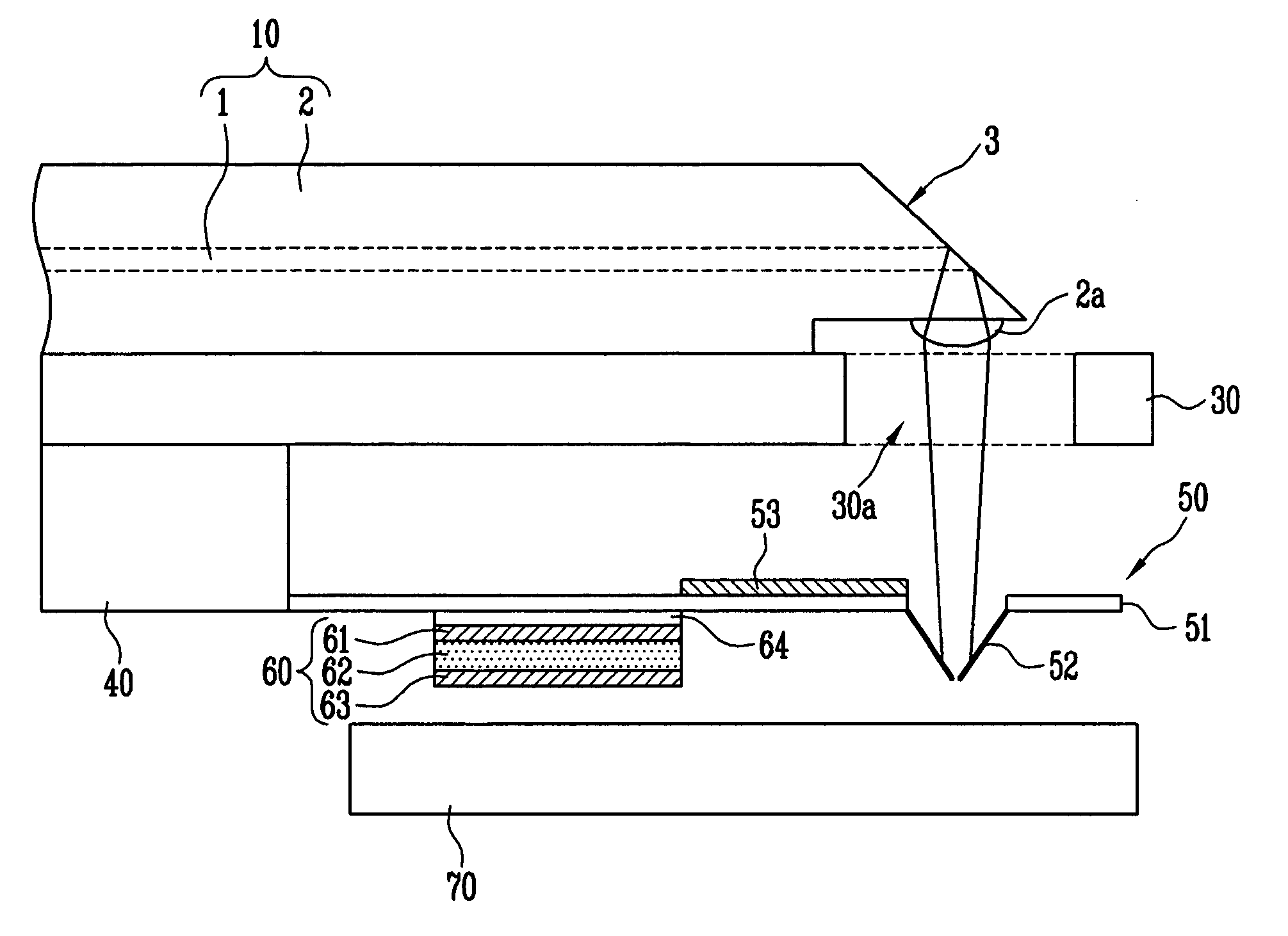
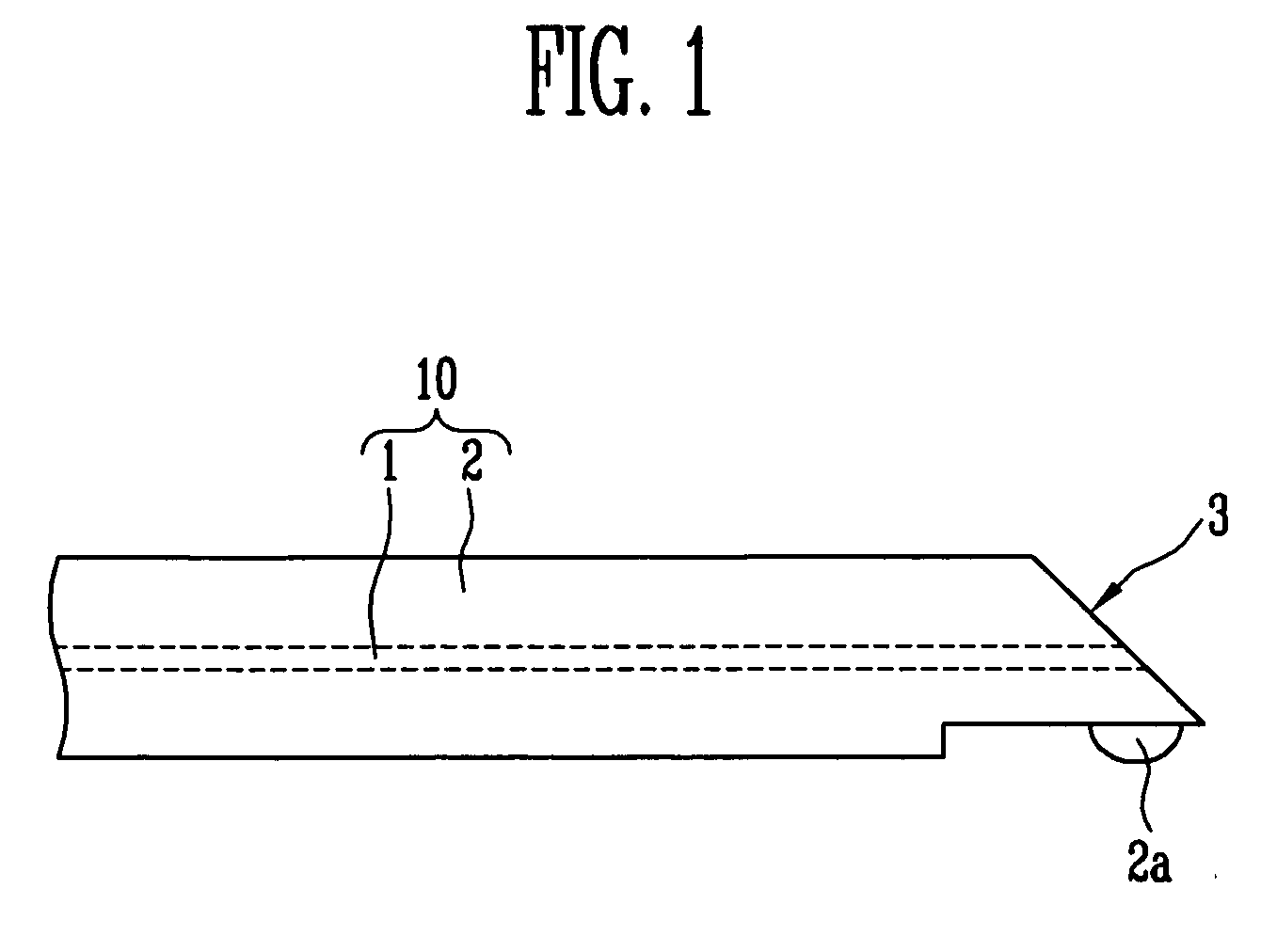
[0034]FIG. 1 is a cross-sectional view of an optical fiber illuminator according to the present invention, in which a mirror 3 for reflecting light in a horizontal direction and a micro lens 2a for focusing the reflected light are provided in one body.

[0035] An optical fibe...


PUM


Abstract

Provided is an optical fiber illuminator used for recording and reading high density optical information according to a near field recording (NFR) scheme, a method of fabricating the optical fiber illuminator, and an optical recording head and recording apparatus having the optical fiber illuminator. The optical fiber illuminator includes: an optical fiber having a core upon which light is incident and a clad that surrounds the core, one end of the optical fiber having a mirror formed in an inclined manner; and a lens formed on an outer surface of the optical fiber for focusing light reflected by the mirror. The optical fiber illuminator has an improved optical arrangement for optical illumination and detection, it is easy to manufacture, its optical input is easy to control, and it can be readily provided in an array form. When an array type optical recording and reading apparatus having an optical recording head and multiple aperture probes adopts the optical fiber illuminator, the resulting simple arrangement and compact size enables size reduction of the overall apparatus, a signal to noise ratio is high, and high density optical information can be recorded and reproduced at an extremely high rate.

Description

CROSS-REFERENCE TO RELATED APPLICATION [0001] This application claims the priority of Korean Patent Application No. 2004-104342 filed on Dec. 10, 2004 and Korean Patent Application No. 2005-34396 filed on Apr. 26, 2005, the disclosure of which is incorporated herein in its entirety by reference. BACKGROUND [0002] 1. Field of the Invention [0003] The present invention relates to an optical fiber illuminator used for recording and reading high density optical information in a near field recording (NFR) scheme, a method of fabricating the optical fiber illuminator, an optical recording head, and an optical recording head and recording apparatus having the optical fiber illuminator. [0004] 2. Discussion of Related Art [0005] In general, optical recording technology that uses focused laser light to record and read information onto / from an optical disk has been the focus of considerable attention as high capacity digital information storage technology. [0006] In conventional technology us...

Claims


Application Information

Patent Timeline
Patent Type & Authority Applications(United States)
IPC IPC(8): G02B6/26
CPCG02B6/241G02B6/262G02B6/32G11B7/1387G01N33/18G06Q50/26G08C17/02G08C2200/00
Inventor PARK, KANG HOKIM, EUN KYOUNGLEE, SUNG Q.
Owner ELECTRONICS & TELECOMM RES INST
Why Eureka
Try Eureka