Linear hybrid brushless servo motor

a brushless servo motor and hybrid technology, applied in the direction of dynamo-electric machines, electrical apparatus, propulsion systems, etc., can solve the problems of low power conversion ratio, low force density and low power conversion ratio of iron-less design, and substantially limited thrust force, etc., to achieve high power conversion ratio, high force density, and high power density

Active Publication Date: 2006-06-22
BALDOR ELECTRIC COMPANY
View PDF31 Cites 26 Cited by
  • Summary
  • Abstract
  • Description
  • Claims
  • Application Information

AI Technical Summary

Benefits of technology

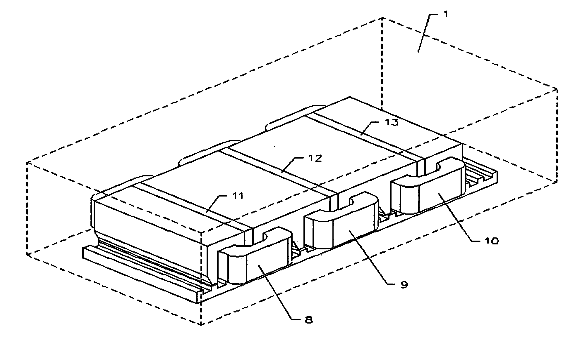
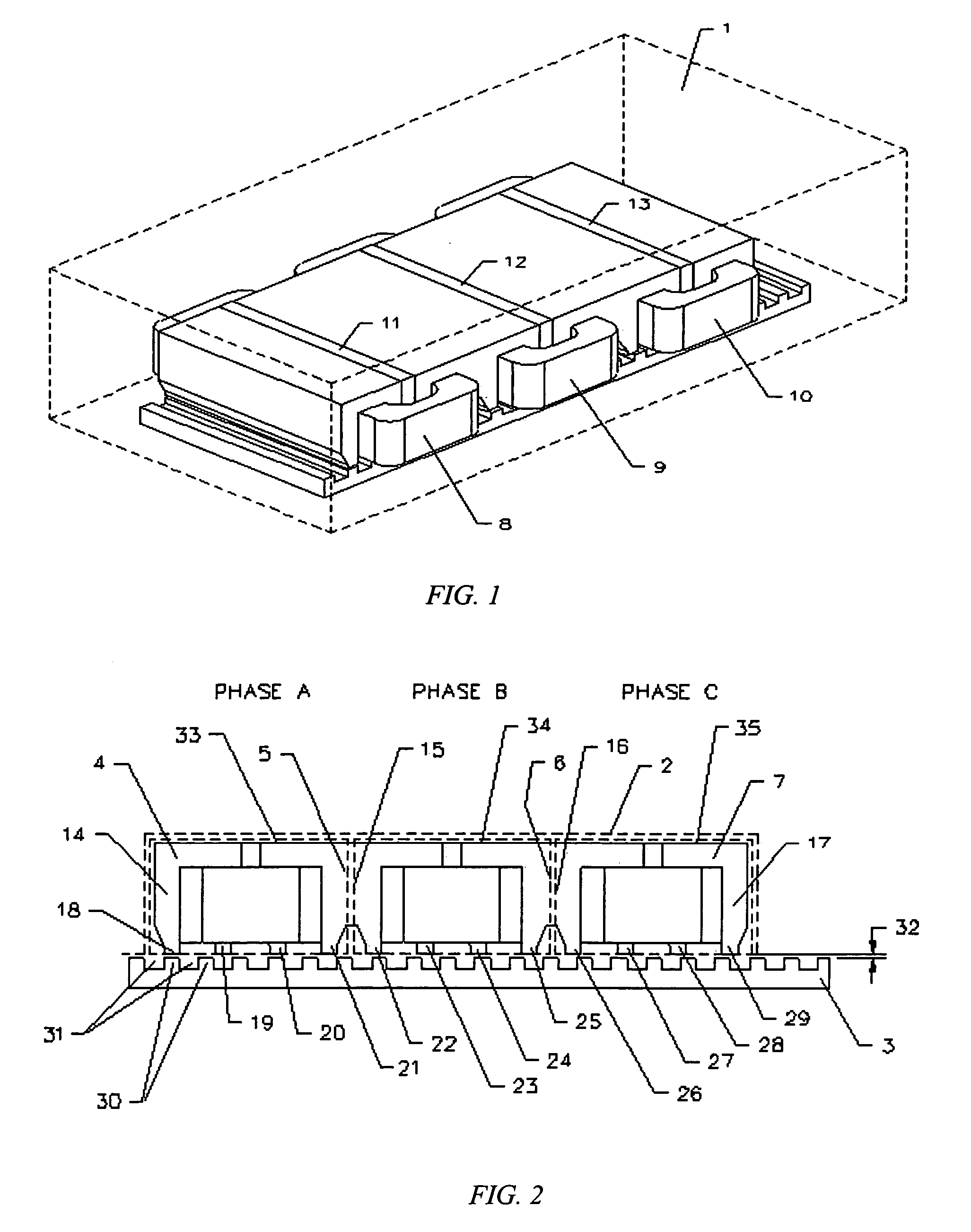
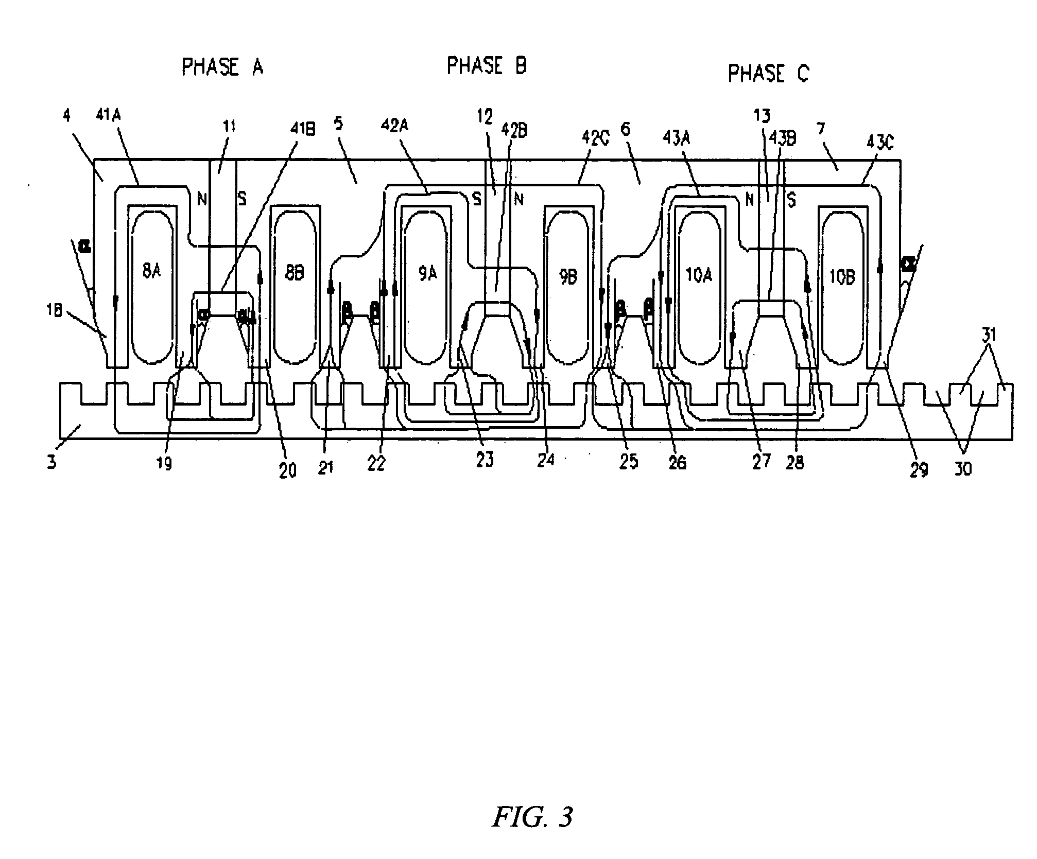
[0003] One object of the present invention is to provide a high performance linear brushless servo motor with high force density and high power conversion ratio with substantially lower manufacturing cost. The present invention yields high electromagnetic coupling and high thrust force with optimal coupling between the forcer and the platen by combining traditional high performance linear brushless PM motor technologies with cost effective linear stepper motor technologies. The present invention preferably uses low cost ferromagnetic steel plates instead of high cost magnet plates as the secondary platen so as to substantially reduce the total cost of manufacturing the motor. However, the forcer and platen can also be made with a laminated plate, which substantially improves the motor's dynamic performance. The motor has three phases offset ±120° and / or ±240° electrically from each other. Supplied by a source of three-phase sinusoidal voltage and current, the forcer interacts with the platen to facilitate operation as a linear three-phase brushless servo motor.

Problems solved by technology

This design can provide high velocities and high acceleration / deceleration(s) during dynamic motion, but the thrust force is substantially limited because of the big air-gap.
The iron-less design also exhibits low force density and low power conversion ratio due to being slot-less and having a relatively big air-gap.
Finally, this design is not cost effective due to the need for many high-cost, high energy product, rare-earth permanent magnets.
It's high manufacturing cost as well as its use of many high-cost rare-earth permanent magnets, however, makes it inherently more expensive than motors using fewer or no magnets, such as stepper motors, induction motors and variable reluctance motors especially for applications necessitating long motion stroke.
Moreover, the iron-core design generates high cogging forces due to interactions between the polarity transition portions of the permanent magnets and both the slots and motor end effects in the primary part.
However, they do not eliminate the need to use magnet track plates comprising many high cost rare earth permanent magnets, which results in the high cost of manufacturing motors with such designs.

Method used


Image

  • Linear hybrid brushless servo motor
  • Linear hybrid brushless servo motor
  • Linear hybrid brushless servo motor

Examples


first embodiment

[0051] The relative pole pitch, T, of the forcer 102 and the platen 103 is substantially identical, and preferably 0.1 mm or greater. The width of the tooth tip of the forcer is preferably in the range of 0.2-0.7*T. The tooth tip width of the forcer 102 and tooth tip width of the platen 103 can be the same or different, but is preferably designed to make the motor system substantially generate the thrust force in the motion direction. Similar to the first embodiment, a method of shifting a stack or a tooth body pair with an optimal electrical angle in each phase assembly also can be used to substantially minimize the existing cogging force and the force ripple generated by the motor system. The electrical angle is preferably in the range of −45° to +45°. The forcer 102 with shifted stack or tooth body pair at some electrical angle causes the central axes of all the alternate tooth tips to be located at a physical distance of (N−θ / 360)*T in each phase assembly. A motor with this conf...

fourth embodiment

[0052]FIG. 16 illustrates a motor with a forcer having a configuration in accordance with the present invention. The forcer 150 comprises six U-shaped stacks 152-157 (preferably ferromagnetic), six permanent magnets 158-163 (preferably rare earth) positioned on the top of the corresponding U-shaped stacks 152-157, respectively, and three ferromagnetic plates 164-166 positioned on the top of corresponding permanent magnets 158-163, respectively. Three phase coils 167-169 are wound in their corresponding stack slots to form three phase assemblies 184-186. Two displacers 191-192 may be positioned between the phase assemblies 184-186 with the appropriate thickness to correct offset electrical angles between phase assemblies 184-186. The central axis of the phase coil 168 of the second phase assembly 185 is offset from the central axis of the phase coil 167 of the first phase assembly 184 by an electrical angle of approximately (T*180°±120°) or by a physical distance of [(N+ / −1 / 3)*T], an...


PUM


Abstract

An improved linear hybrid brushless servo motor is disclosed. The motor comprises a forcer and a platen. The forcer has a plurality of stacks, permanent magnets, and coils which form a three-phase motor. The platen has a low cost ferromagnetic steel plate. The stacks, permanent magnets and phase coils of the forcer are specially designed to have the optimal electromagnetic coupling between the forcer and platen to achieve a high force density servomotor. In one embodiment, two E-shaped stacks are used to physically couple two phases to substantially minimize the unexpected cogging force and force ripple. Three other forcer configurations which achieve a three-phase, highly cost effective and high force density linear hybrid brushless servo motor are also disclosed.

Description

BACKGROUND OF THE INVENTION [0001] This invention relates generally to linear motor positioning and motion systems and methods, and more particularly to an improved linear hybrid brushless servo motor having high force density, high electrical power conversion ratio, and considerably low manufacturing cost. [0002] Conventional linear brushless permanent magnet (PM) servo motors used in the prior art have either an ‘iron-less design’, comprising slot-less moving coil parts and a plurality of permanent magnets on stationary iron core plates (as described in U.S. Pat. No. 6,160,327), or an ‘iron-core design’ comprising a laminated iron core having slots and teeth and phase winding coils in the moving part and a plurality of permanent magnets on the stationary iron-core plate (as described in U.S. Pat. No. 5,642,013, U.S. Pat. No. 5,910,691 and U.S. Pat. No. 6,242,822). The iron-less design has the advantage of zero cogging, zero attractive force and very little mass in the moving part....

Claims


Application Information

Patent Timeline
Patent Type & Authority Applications(United States)
IPC IPC(8): H02K41/00
CPCH02K41/033H02K2213/03
Inventor LIN, HUAIHEILIG, JOHN ANDREW
Owner BALDOR ELECTRIC COMPANY
Why Eureka
Try Eureka