
Apparatus and method for producing hydrogen

Inactive Publication Date: 2006-06-29
TEXACO INC
View PDF56 Cites 20 Cited by
  • Summary
  • Abstract
  • Description
  • Claims
  • Application Information

AI Technical Summary

Benefits of technology

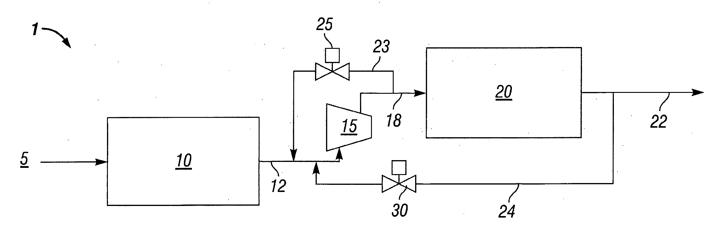
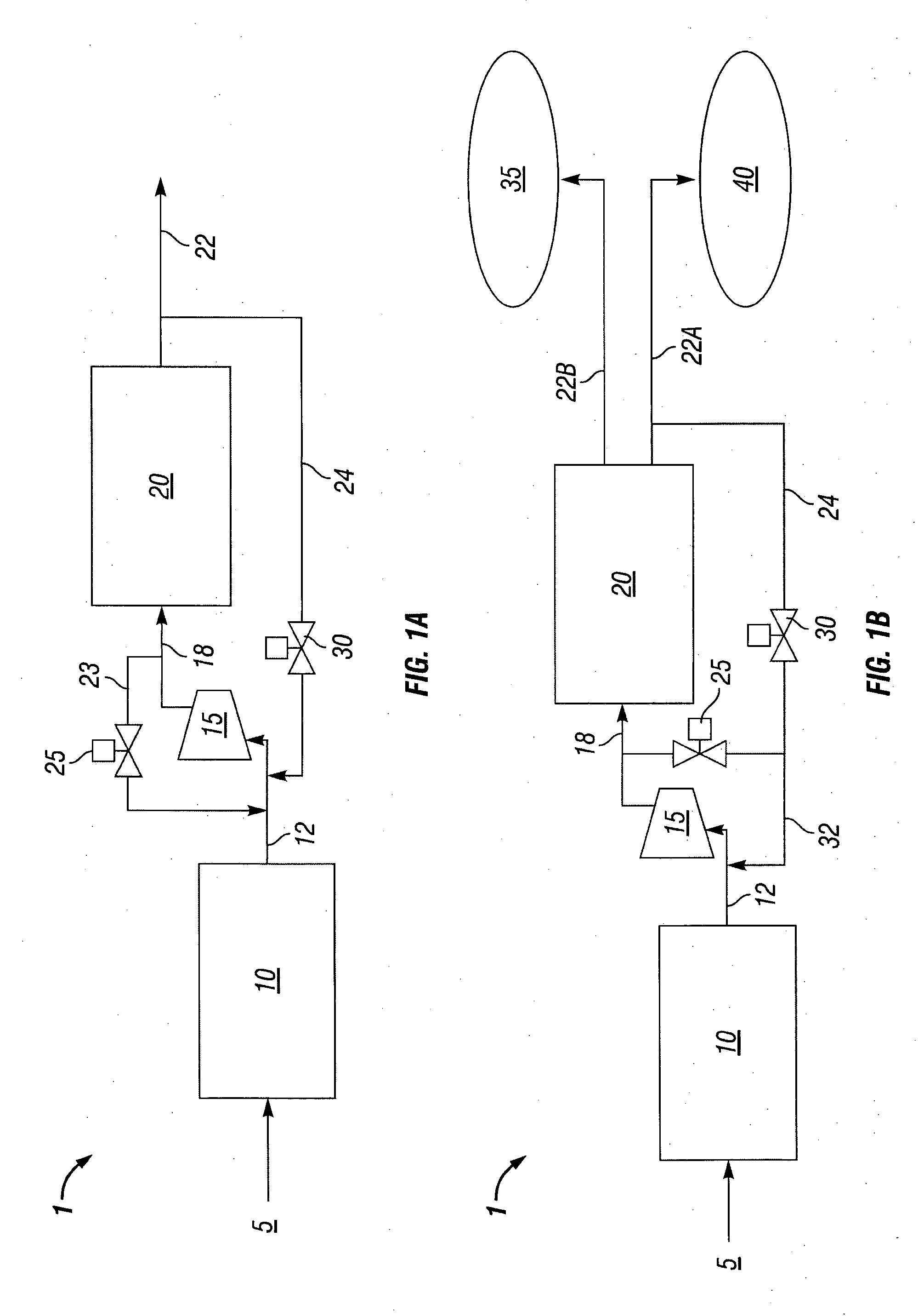
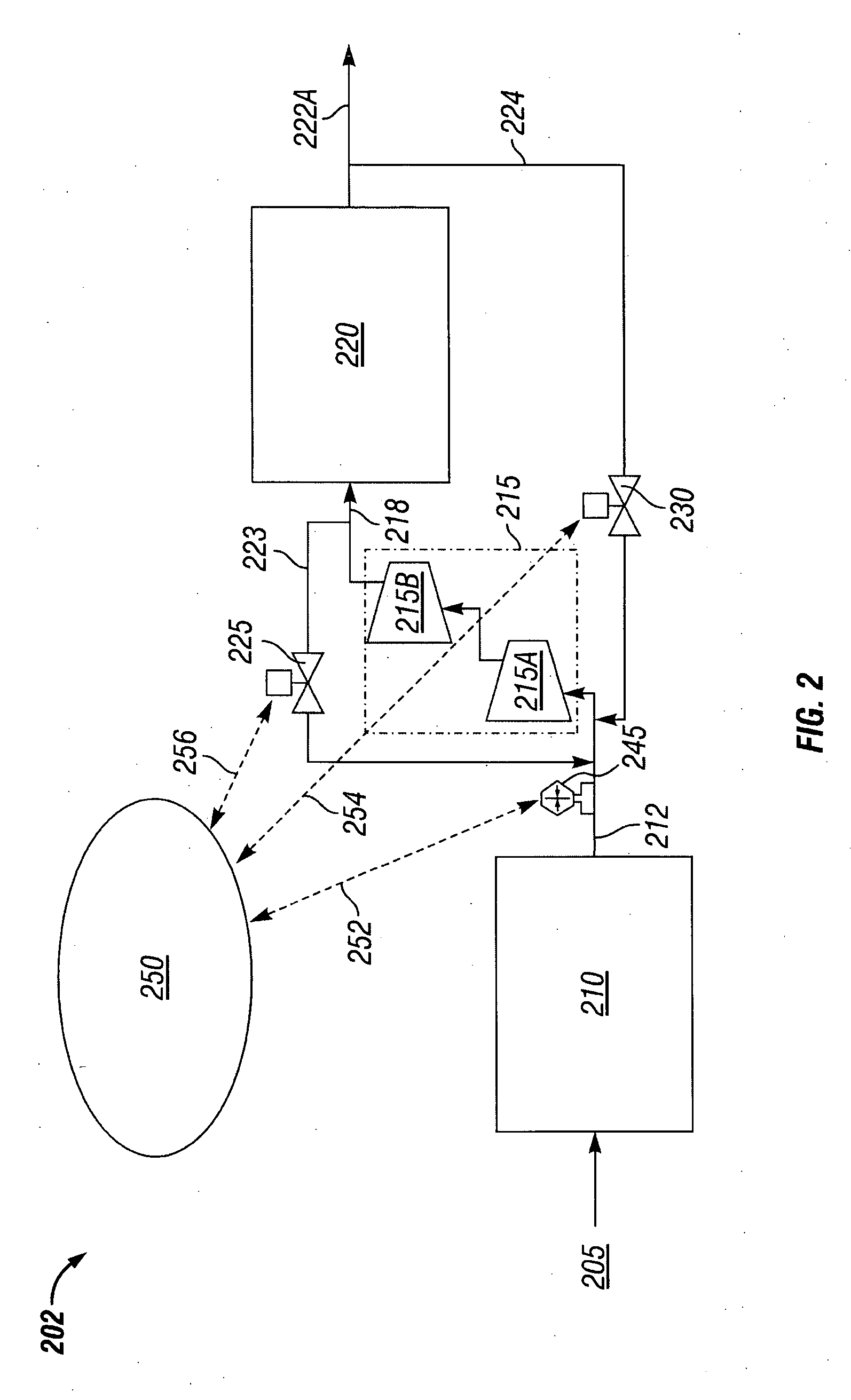
[0005] In one aspect of the present invention, an apparatus for producing hydrogen is provided. The apparatus includes a fuel processor for converting a fuel to a reformate comprising hydrogen and an impurity, the reformate having fluctuations in pressure and / or flow rate. Means for reducing the fluctuations in pressure and / or flow rate are disposed downstream of the fuel processor. A compression unit is also disposed downstream of the fuel processor for receiving the reformate and producing a compressed reformate. A purification unit is disposed downstream of the compression unit for receiving at least a portion of the compressed reformate and producing a hydrogen-enriched reformate. The means for reducing fluctuations in the pressure and / or flow rate of the reformate can include one or more of a buffer disposed intermediate of the fuel processor and the compression unit, and a conduit capable of providing a controlled flow of a supplemental fluid to an inlet of the compression unit. The supplemental fluid can include one or more of a compressed reformate and a hydrogen-enriched reformate. Optionally, the apparatus can include means for regulating power to the compression unit.
[0006] In another aspect of the present invention, an apparatus for producing hydrogen is provided. The apparatus includes a fuel processor for converting a fuel to a reformate comprising hydrogen and an impurity, the reformate having fluctuations in pressure and / or flow rate. Means for reducing the fluctuations in pressure and / or flow rate are disposed downstream of the fuel processor. A compression unit is also disposed downstream of the fuel processor for receiving the reformate and producing a compressed reformate. A storage unit is disposed downstream of the compression unit that is capable of receiving at least a portion of the compressed reformate and storing the compressed reformate. The means for reducing fluctuations in pressure and / or flow rate can include one or more of a buffer disposed intermediate of the fuel processor and the compression unit, and a conduit that is capable of providing a controlled flow of a supplemental fluid to an inlet of the compression unit. The supplemental fluid can include one or more of a compressed reformate and hydrogen-enriched reformate. Optionally, the apparatus can include means for regulating power to the compression unit.

Problems solved by technology

While there is wide-spread consumption of hydrogen and great potential for even more, a disadvantage which inhibits further increases in hydrogen consumption is the absence of an infrastructure that can provide generation, storage and widespread distribution of hydrogen.
However, in addition to the desired hydrogen product, fuel reformers typically produce undesirable impurities that reduce the value of the reformed product.
Although purification technologies can effectively provide a purified hydrogen product, many require compression of the reformate to an initial high pressure.
Such consistency can be particularly difficult to achieve where the hydrogen is a reformate derived from a fuel processor.
Adverse consequences due to fluctuations in reformate pressure and / or flow rate can include an upset within the fuel processor from which the hydrogen reformate is derived and the formation of a vacuum at the inlet to a compression unit creating the potential for drawing atmospheric gases into the process stream.
Moreover, where the compressed reformate is to be purified in a purification unit such as a pressure swing adsorption unit, such fluctuations can negatively impact the purity of the hydrogen-enriched reformate produced.

Method used


Image

  • Apparatus and method for producing hydrogen
  • Apparatus and method for producing hydrogen
  • Apparatus and method for producing hydrogen

Examples


Embodiment Construction

[0017] Illustrative embodiments of the invention are described below. In the interest of clarity, not all features of an actual embodiment are described in this specification. It will of course be appreciated that in the development of any such actual embodiment, numerous implementation-specific decisions must be made to achieve the developers' specific goals, such as compliance with system-related and business-related constraints, which will vary from one implementation to another. Moreover it will be appreciated that such a development effort might be complex and time-consuming, but would nevertheless be a routine undertaking for those of ordinary skill in the art having the benefit of this disclosure.

[0018] An apparatus of the present invention includes a fuel processor for converting a fuel to a reformate comprising hydrogen and an impurity. The flow of reformate can have fluctuations in pressure and / or flow rate and means are provided for reducing the fluctuations. The means f...


PUM


Abstract

An apparatus and method for producing a hydrogen-enriched reformate. The apparatus includes a fuel processor for converting a fuel to a reformate having fluctuations in pressure and or flow rate, means for reducing the fluctuations, a compression unit for compressing the reformate and one or more of a purification unit and a storage unit downstream of a compression unit. Means for reducing the fluctuations in the reformate can include one or more of a buffer and a conduit for providing a controlled flow of a supplemental fluid to an inlet of the compression unit. The supplemental fluid can include the compressed reformate, a hydrogen-enriched reformate, and mixtures thereof. The apparatus can include means for regulating power to the compression unit that can incrementally increase power to the compression unit particularly during start up. The purification unit can include one or more of a hydrogen selective membrane and a pressure swing adsorption unit. Methods for producing hydrogen are also disclosed.

Description

FIELD OF THE INVENTION [0001] The present invention relates to the field of fuel processing wherein hydrocarbon-based fuels are converted to a hydrogen-enriched reformate for ultimate use in hydrogen-consuming devices and processes. An apparatus and method of the present invention provide a hydrogen-enriched reformate of high purity by removing impurities through various purification technologies such as pressure swing adsorption, membrane separation and the like that require the reformate to be at a relatively high initial pressure. The compression of a hydrogen-rich reformate for storage purposes is also addressed. BACKGROUND OF THE INVENTION [0002] Hydrogen is utilized in a wide variety of industries ranging from aerospace to food production to oil and gas production and refining. Hydrogen is used in these industries as a propellant, an atmosphere, a carrier gas, a diluent gas, a fuel component for combustion reactions, a fuel for fuel cells, as well as a reducing agent in numero...

Claims


Application Information

Patent Timeline
IPC IPC(8): C01B3/24
CPCC01B3/38C01B3/501C01B3/56C01B2203/0233C01B2203/0244C01B2203/0261C01B2203/0283C01B2203/0405C01B2203/043C01B2203/044C01B2203/0455C01B2203/047C01B2203/0485C01B2203/066C01B2203/1241C01B2203/16C01B2203/1604C01B2203/1628
Inventor KENEFAKE, DEAN A.WHEAT, W. SPENCERSUN, HONGQIAOBALASUBRAMANIAN, BHASKARMIRKOVIC, VESNA R.CASEY, DANIEL G.
Owner TEXACO INC
Learn More