Method for producing heat exchanger tubes, which consist of half-tubes or complete tubes and which are provided for recuperative exhaust gas heat exchanger

Inactive Publication Date: 2006-06-29
MTU AERO ENGINES GMBH
View PDF6 Cites 43 Cited by
  • Summary
  • Abstract
  • Description
  • Claims
  • Application Information

AI Technical Summary

Benefits of technology

[0015] Such a precision casting process may provide that it combines a high reproducibility with consistently high quality and low production costs.
[0020] The use of a precision casting process for the production of heat-exchanger tubes from half-tubes or tubes may provide for an inexpensive, quick and qualitatively high-grade production of such tube components.

Problems solved by technology

The formation of such a large number of openings in the surface of the forged half-tubes proves to be extremely cost-intensive and time-consuming.
Apart from the high cost, the EDM process has a further disadvantage.
These layers have to be removed before the high-temperature soldering to be carried out subsequently for soldering the lancets into the half-tubes, which proves to be a disadvantage and is complicated.
The narrow soldering gaps and small tolerances (±0.05 mm) required for the high-temperature soldering often cannot be achieved with existing recast layers for economic reasons (a slow fine processing stage is necessary).
This method is costly however in terms of installation and tooling, and has capital-intensive equipment costs.
Also, the electrolyte in this process is typically an oxidizing agent, for example, sodium nitrate or sodium chloride, which constitutes a health and security risk, and the by-products of the process are classified as toxic waste.
To summarize, this means that the formation of the openings in the surface of the forged half-tubes is a high-risk operation in terms of technology, time and cost in the production of the overall recuperative waste gas heat exchanger.

Method used


Image

  • Method for producing heat exchanger tubes, which consist of half-tubes or complete tubes and which are provided for recuperative exhaust gas heat exchanger
  • Method for producing heat exchanger tubes, which consist of half-tubes or complete tubes and which are provided for recuperative exhaust gas heat exchanger
  • Method for producing heat exchanger tubes, which consist of half-tubes or complete tubes and which are provided for recuperative exhaust gas heat exchanger

Examples


Embodiment Construction

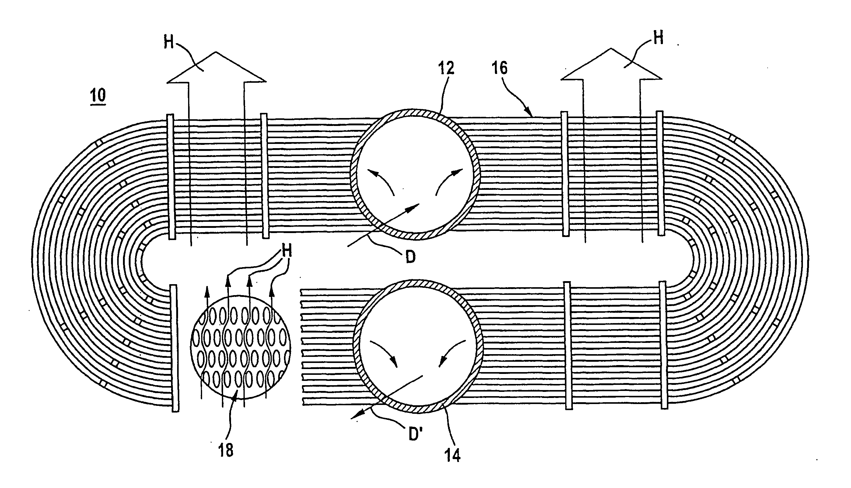
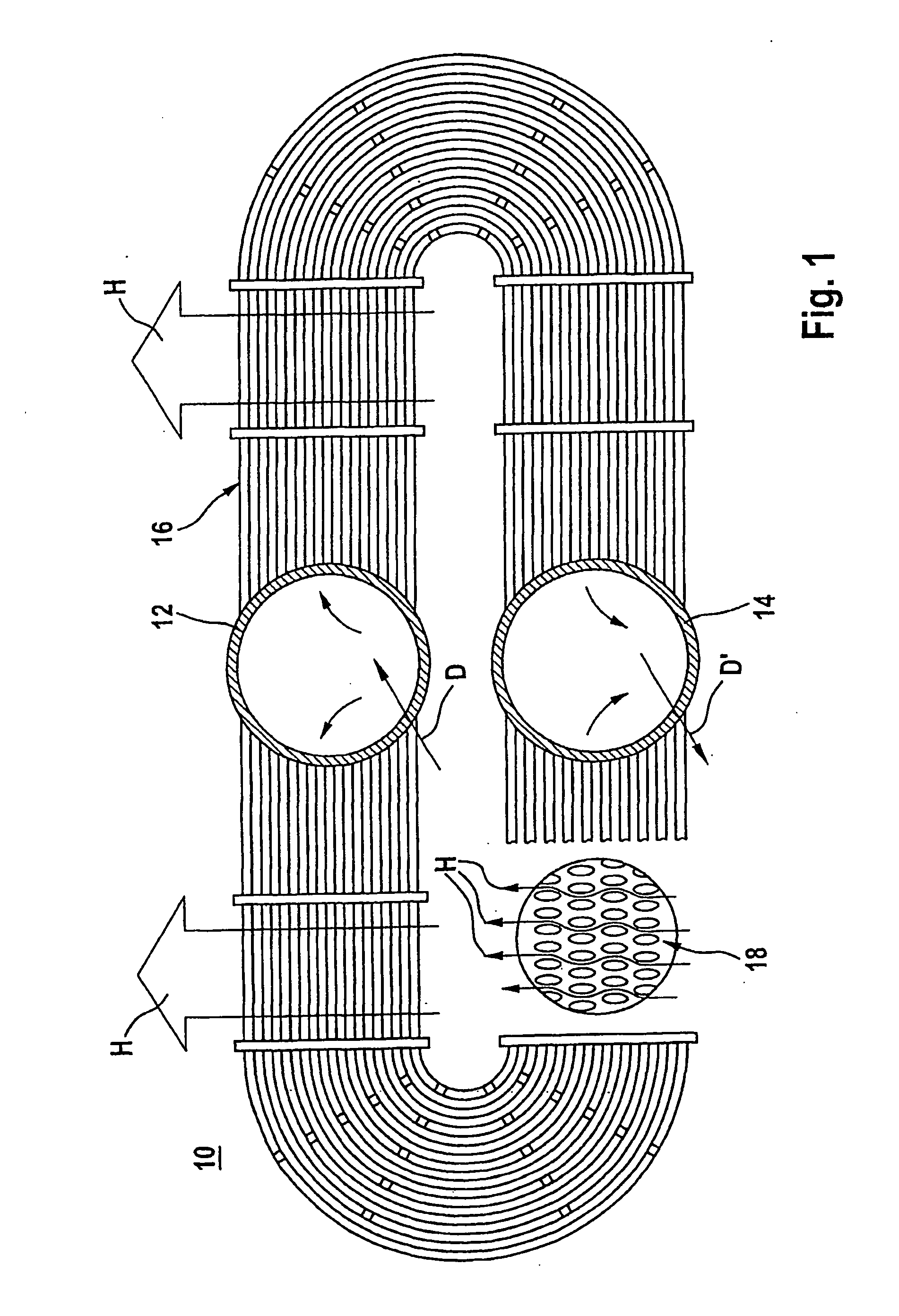
[0025] A recuperative waste gas heat exchanger of a gas turbine plant, identified overall in FIG. 1 by the reference numeral 10, includes a distributor tube 12, a collecting tube 14 arranged parallel thereto, as well as a cross-counterflow matrix 16 protruding laterally thereto in a U-shape. For simplicity, the distributor tube 12 and collecting tube 14 are identified hereinafter as heat exchanger tubes.

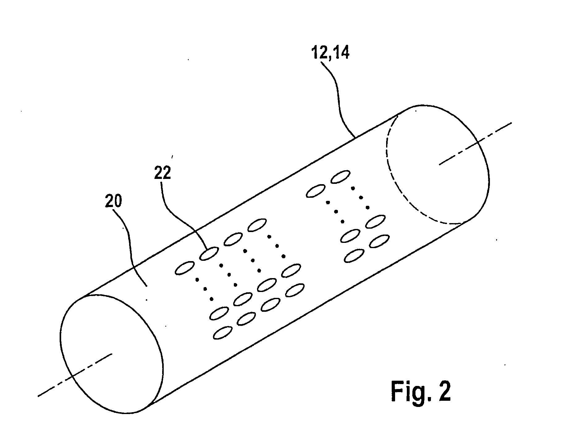
[0026] From the cross-sectional view of the cross-counterflow matrix 16 illustrated in the bottom left-hand corner of FIG. 1, it can be seen that the cross-counterflow matrix 16 includes a plurality of elliptical small tubes or lancets 18. The lancets 18 are in each case secured to the distributor tube 12 and collecting tube 14. They correspond to the openings / holes 22, not visible in this view, made for this purpose in the surface of the distributor tube 12 and the collecting tube 14 (cf. FIG. 2).

[0027] The mode of operation of the recuperative waste gas heat exchanger described h...


PUM

PropertyMeasurementUnit
Lengthaaaaaaaaaa
Lengthaaaaaaaaaa
Lengthaaaaaaaaaa

Abstract

In a process for the production of half-tubes or tubes of a recuperative waste gas heat exchanger using a precision casting process, the half-tubes or tubes consisting of a high-temperature-resistant metallic material have a plurality of elliptical openings passing through their surface.

Description

FIELD OF THE INVENTION [0001] The present invention relates to a process for the production of half-tubes or tubes of a metallic, high-temperature-resistant material with a plurality of openings passing through their surface, for the fabrication of heat exchanger tubes for recuperative waste gas heat exchangers, as well as half-tubes / tubes produced by this process. BACKGROUND INFORMATION [0002] As is conventional, the recuperative waste gas heat exchangers used in gas turbine plants include, in addition to a heat exchanger housing, a distributor tube for feeding the “cold” air conveyed from a compressor into a so-called cross-counterflow matrix through which hot turbine waste gas flows, and a collecting tube for passing the now heated-up “hot” compressor air to a suitable consumer, for example, the combustion chamber of the gas turbine plant. For simplicity, the distributor tube as well as the collecting tube will hereinafter also be referred to as heat exchanger tube. [0003] The fe...

Claims


Application Information

Patent Timeline
IPC IPC(8): F28F9/02B23P15/26B22C7/02B22C9/04B22DB22D15/02F28D7/00
CPCB22C7/02Y10T29/49389B22C9/04F28D7/06F28F2275/06
Inventor STEINHAUSER, LUDWIG
Owner MTU AERO ENGINES GMBH
Why Eureka
Try Eureka