
Methods of forming non-volatile semiconductor memory devices using prominences and trenches, and devices so formed

a semiconductor memory and non-volatile technology, applied in semiconductor devices, instruments, electrical appliances, etc., can solve problems such as affecting device reliability, deteriorating transistor characteristics, and increasing leakage current, so as to enhance device isolation layer filling properties, enhance device reliability, and increase width

Inactive Publication Date: 2006-06-29
SAMSUNG ELECTRONICS CO LTD
View PDF8 Cites 74 Cited by
  • Summary
  • Abstract
  • Description
  • Claims
  • Application Information

AI Technical Summary

Benefits of technology

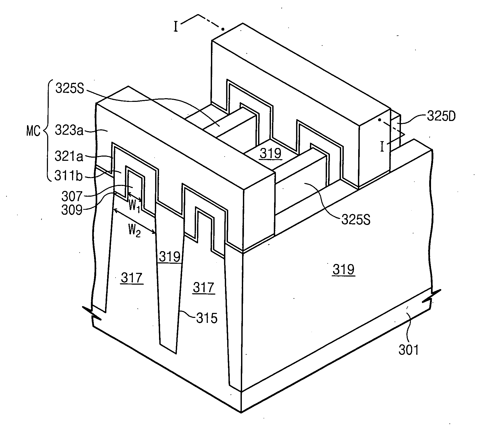
[0014] According to the above methods, since the depression and prominence are used as an active region, the width of the active region can be increased. Also, in the etch process for forming the trench, since the floating gate protects the depression and prominence serving as the active region, the depression and prominence can be prevented from being etched. Accordingly, the active region with an increased width and a superior electrical characteristic can be provided.
[0021] Also, in some embodiments, the device isolation layer is positioned higher than a bottom of the depression. This can reduce or prevent the control gate and the semiconductor substrate at the bottom of the depression from being electrically short-circuited when a high voltage for the programming / erase operation is applied to the control gate.
[0024] According to the above methods of forming the MOSFET, the lower conductive pattern can protect the depression and prominence serving as the active region during the etch step of forming the trench.
[0025] Also, since the trench for the device isolation is formed in self-alignment with the lower conductive pattern, a part of the depression as well as the prominence serves as a channel, so that a current driving capability of the MOSFET may be enhanced.
[0031] Since the first prominence serves as a channel region, in some embodiments, the first prominence is constant in width to allow enhanced device reliability. To potentially enhance the filling property of the device isolation layer, the second prominence may have a width increasing as it extends to a lower side.
[0032] In some embodiments, the upper surface of the device isolation layer be positioned higher than the upper surface of the second prominence. Accordingly, when a high voltage for the programming / erase operation is applied to the second conductive layer, an electrical short-circuit between the second conductive layer and the upper surface of the second prominence can be effectively reduced or prevented.

Problems solved by technology

As the integration density continues to increase, a variety of problems deteriorating the transistor characteristics may occur.
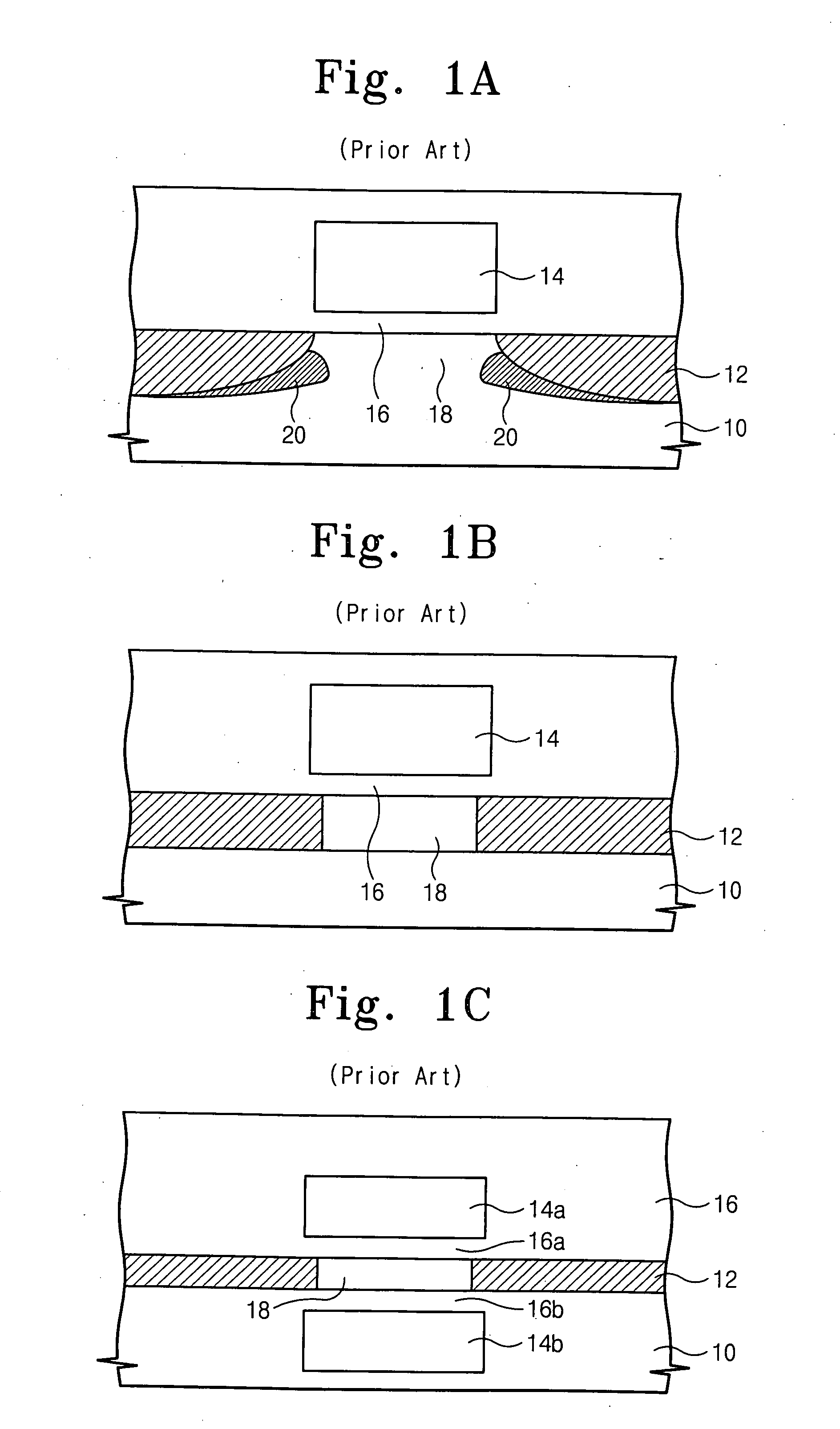
For instance, as the channel length of the FET is gradually decreased, problems including short channel effects, such as punch-through, drain induced barrier lowering (DIBL), subthreshold swing and the like, an increase in parasitic capacitance (junction capacitance) between the junction region and a substrate, a leakage current increase, etc., may occur.
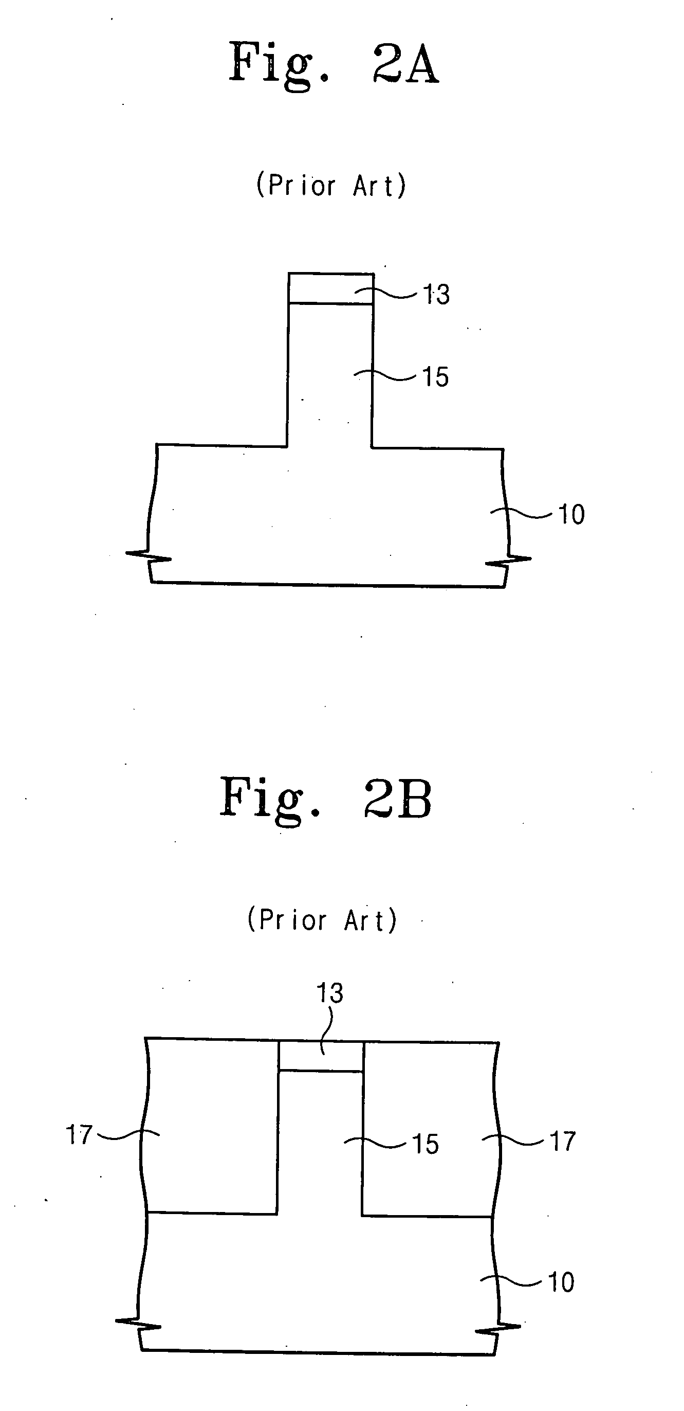
Also, while the step of partially removing the device isolation layer 17 is performed, the semiconductor fin 15 may be etch-damaged, so that the device reliability may be impacted.
The SOI substrate may be expensive and may show a floating effect, compared with bulk silicon substrates.

Method used


Image

  • Methods of forming non-volatile semiconductor memory devices using prominences and trenches, and devices so formed
  • Methods of forming non-volatile semiconductor memory devices using prominences and trenches, and devices so formed
  • Methods of forming non-volatile semiconductor memory devices using prominences and trenches, and devices so formed

Examples


Embodiment Construction

[0044] The invention will be described more fully hereinafter with reference to the accompanying drawings, in which example embodiments of the invention are shown. This invention may, however, be embodied in many different forms and should not be construed as limited to the example embodiments set forth herein. Rather, the disclosed embodiments are provided so that this disclosure will be thorough and complete, and will fully convey the scope of the invention to those skilled in the art. In the drawings, the size and relative sizes of layers and regions may be exaggerated for clarity. Moreover, each embodiment described and illustrated herein includes its complementary conductivity type embodiment as well. Like numbers refer to like elements throughout.

[0045] It will be understood that when an element or layer is referred to as being “on”, “connected to” and / or “coupled to” another element or layer, it can be directly on, connected or coupled to the other element or layer or interv...


PUM


Abstract

A semiconductor substrate is patterned to form a depression and prominence. A floating gate is formed so as to cover at least both sidewalls of the prominence of the depression and prominence, and is then etched to form a trench for a device isolation self-aligned with the floating gate. Related structures are also described.

Description

CROSS-REFERENCE TO RELATED APPLICATION [0001] This application claims the benefit under 35 USC § 119 of Korean Patent Application No. 10-2004-0113977, filed on Dec. 28, 2004, the disclosure of which is hereby incorporated herein by reference in its entirety as if set forth fully herein. FIELD OF THE INVENTION [0002] The present invention relates to semiconductor devices and methods of forming the same, and more particularly, to non-volatile semiconductor memory devices and methods of forming the same. BACKGROUND OF THE INVENTION [0003] Silicon-based integrated circuit (IC) devices, in particular, a metal-oxide semiconductor (MOS) device, e.g., a field effect transistor (FET) or a metal-oxide semiconductor field effect transistor (MOSFET) are widely used in many consumer and commercial applications. These devices have been fabricated such that the throughput can decrease and a high speed, a high integrity and an enhanced performance can be obtained. [0004]FIG. 1A shows a conventional...

Claims


Application Information

Patent Timeline
IPC IPC(8): H01L21/336
CPCG11C16/0483H01L27/115H01L27/11521H01L29/7851H10B69/00H10B41/30H10B41/35
Inventor HONG, SEUNG-WAN
Owner SAMSUNG ELECTRONICS CO LTD
Learn More