Probe for a scanning microscope

a scanning microscope and probe technology, applied in the direction of instruments, mechanical roughness/irregularity measurements, measurement devices, etc., can solve the problem of physical limits to the sharpness of the tip end of the above-described protruding portion, the tendency of the carbon nanotube to fall off the protruding portion, etc., to achieve high sensitivity, high sensitivity, high sensitivity

Inactive Publication Date: 2006-07-13
NAKAYAMA YOSHIKAZU +2
View PDF1 Cites 16 Cited by
  • Summary
  • Abstract
  • Description
  • Claims
  • Application Information

AI Technical Summary

Benefits of technology

[0029] In the fifth aspect of the present invention, since the conductive covering film of the above-described fourth aspect is formed so as to cover the tip end portion and tip end of the nanotube, the nanotube probe needle can be endowed with the properties of a conductive substance. By using a probe that has such specified properties, it is possible to detect, with a high sensitivity, specified physical properties of a sample surface that is highly sensitive.
[0030] In the sixth aspect of the present invention, a conductive film that is extended so as to cover the tip end portion of the nanotube is constructed from a magnetic substance; accordingly, the nanotube probe needle can be endowed with the property of detecting the magnetism of the sample. In other words, the nanotube probe needle can be used as a probe needle for a magnetic force microscope (MFM). Furthermore, by scanning the sample surface by the nanotube probe needle, information relating to the magnetism of the sample surface at the atomic level is detected with a high sensitivity, so that a high-resolution magnetic image can be acquired. For example, this magnetic conductive covering film can be constructed from a ferromagnetic substance such as Fe, Co or Ni and can measure magnetic information relating to the sample surface with a high sensitivity.
[0031] In the seventh aspect of the present invention, since the conductive film which is extended so as to cover the tip end portion of the nanotube is constructed from a palladium covering film to which ferromagnetic metal atoms are added, the nanotube probe needle can be endowed with the property of detecting the magnetism of the sample. More specifically, the nanotube probe needle can be used as a probe needle for a magnetic force microscope (MFM). Ferromagnetic metals have a good compatibility with palladium and have the property of forming a uniform solution with palladium. Furthermore, since a palladium covering film containing ferromagnetic metals bonds strongly with the nanotube and the palladium covering film, a probe needle for a magnetic force microscope (MFM) can be provided which has high-durability performance with no peeling of the above-described film from the nanotube probe needle. Furthermore, by scanning the sample surface by the nanotube probe needle, information relating to the magnetism of the sample surface at the atomic level can be detected with a high sensitivity, so that a high-resolution magnetic image can be acquired.
[0032] In the eighth aspect of the present invention, since the palladium covering film additionally covers the cantilever surface including all or part of the base end portion of the nanotube, in contrast to a conventional nanotube probe in which a nanotube is fastened to the surface of the cantilever, the nanotube and palladium covering film can be simply endowed with conductivity. While the nanotube was fastened by first forming a palladium covering film on the cantilever surface in the first aspect, this sixth aspect is characterized in that a palladium covering film is formed after the nanotube is fastened to the cantilever. Even if the palladium covering film is thus formed afterward, the conductivity performance between the palladium covering film and the nanotube is ensured. Since the nanotube is already fastened to the cantilever surface by a coating film or fusion, and since a palladium covering film is formed on top of this, the fastening strength of the nanotube is greatly increased. At the same time, the conductivity performance between the nanotube and the palladium covering film is realized in the same manner as in the first aspect, so that a great improvement in fastening strength and conductivity is accomplished.

Problems solved by technology

However, there are limits to the miniaturization that can be achieved even in electric current semiconductor working techniques; accordingly, there are also physical limits to the sharpness of the tip end of the above-described protruding portion.
The probe of these researchers was a break-through probe; however, this probe showed a tendency for the carbon nanotube to fall off of the protruding portion.
Accordingly, even if a conductive carbon nanotube is fastened to the protruding portion of such a cantilever, it is difficult to apply a voltage across the nanotube probe needle and the sample, or to cause an electric current to flow through the probe needle, since the cantilever itself does not possess conductivity.
In cases where the probe does not possess conductivity, this means that the use of the probe is severely restricted.
More specifically, in conventional methods, the sample surface shape is merely detected via the amount of mechanical deformation of the nanotube; information relating to physical properties such as the mechanical characteristics of the sample surface and the like cannot be obtained.
However, in cases where the probe does not possess conductivity, such voltage application and electric current flow are impossible, so that the electrical operation of the nanotube is impossible, thus limiting the effectiveness of the probe.
For example, in a probe in which electrical operation is impossible, limits arise in terms of the operability in depositing atoms, moving atoms and extracting atoms on the sample surface.
The inability to perform electrical operations on a nanotube leads to a restriction of the future possibilities of the probe itself.
However, carbon nanotubes consist of a carbonaceous material, and there has been almost no research on metal materials that can be tightly bonded to carbon nanotubes.
Accordingly, if the wrong metal material is selected, the carbon nanotube may insulated from the metal coating film so that the electrical continuity is interrupted, or the conductivity may be insufficient.

Method used


Image

  • Probe for a scanning microscope
  • Probe for a scanning microscope
  • Probe for a scanning microscope

Examples


first embodiment

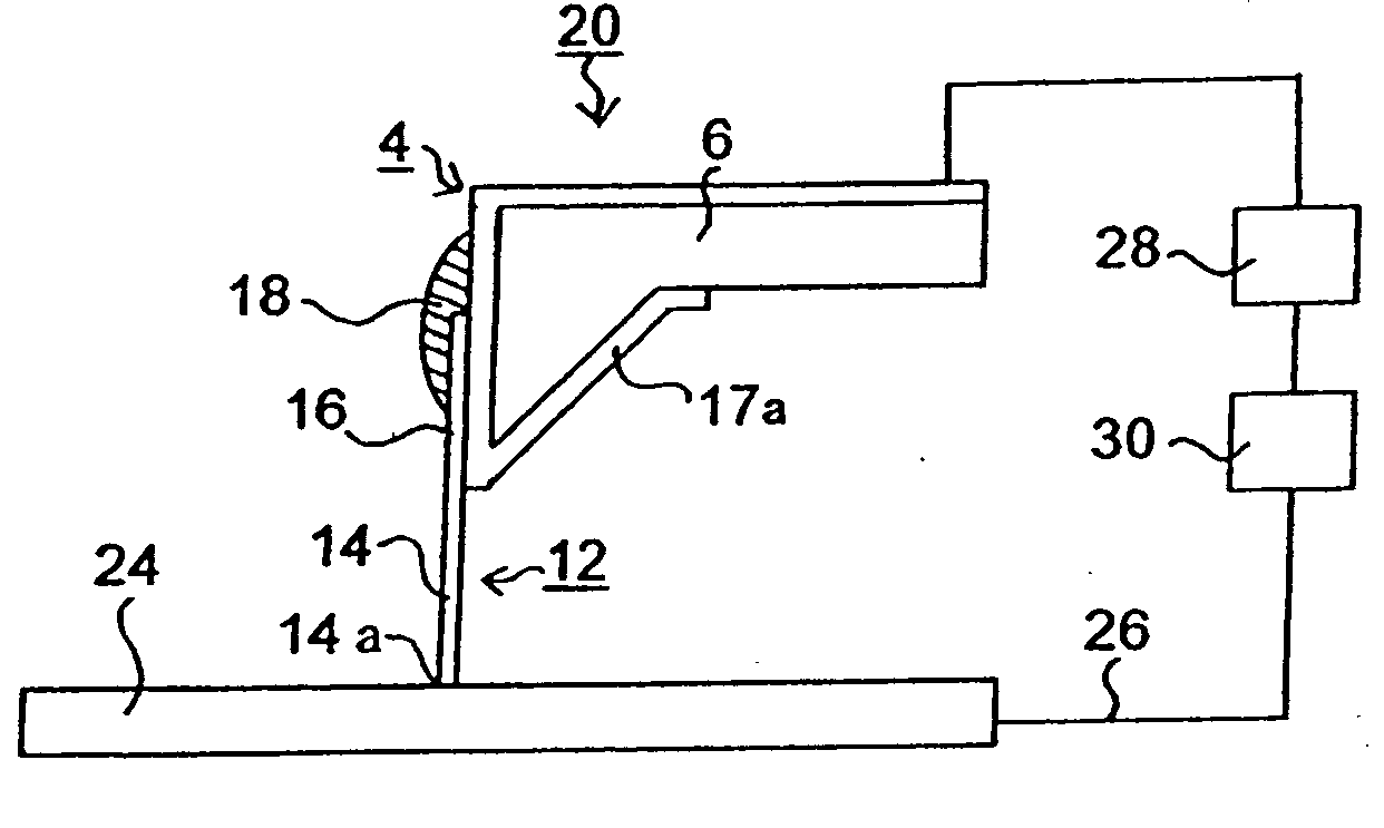
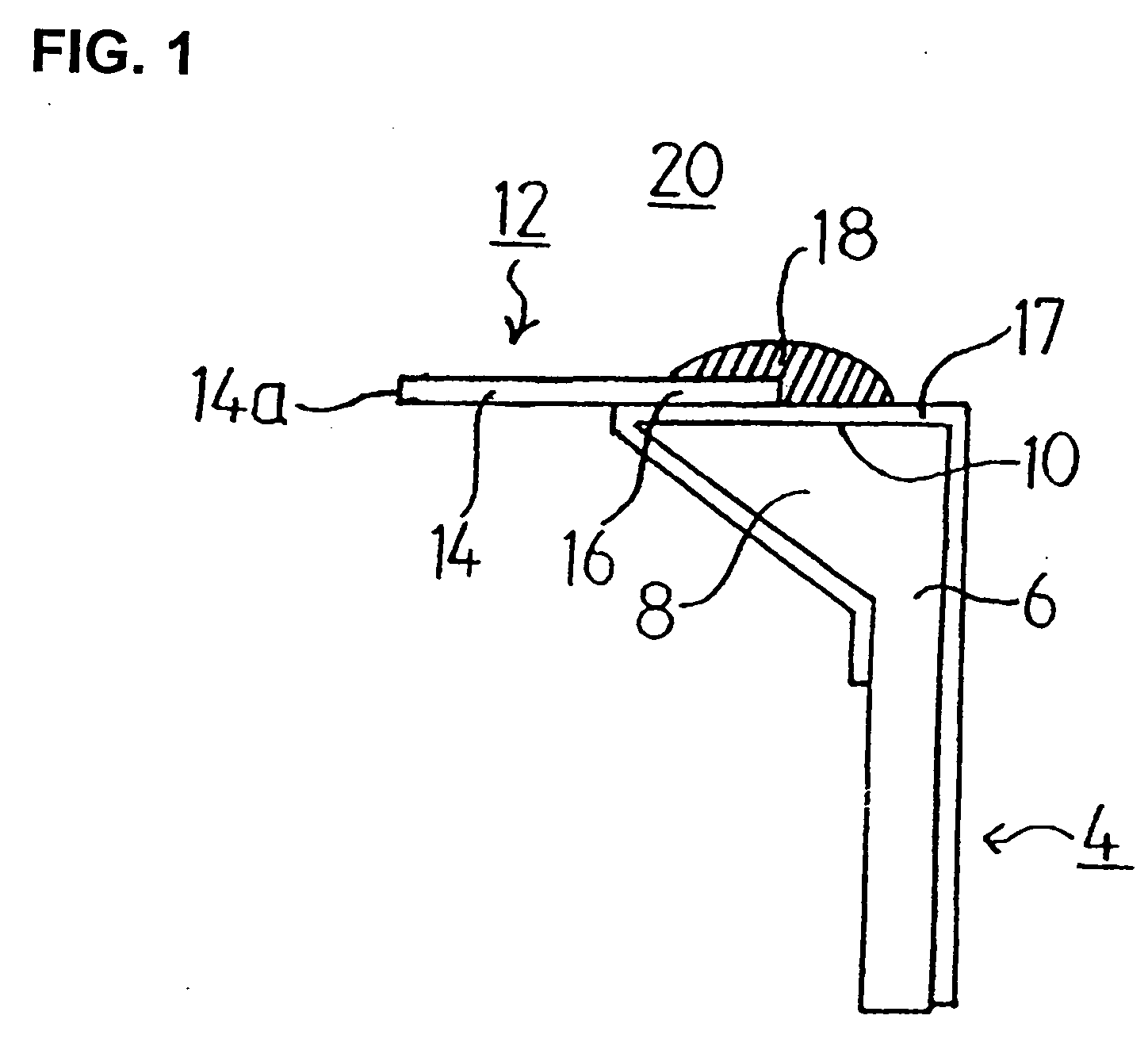
[0047]FIG. 1 is a schematic explanatory diagram of the scanning microscope probe of the present invention.

[0048] The cantilever 4 is a member that is used as an AFM probe needle; and this cantilever 4 is comprised of a cantilever main portion 6 and a protruding portion 8 that is formed in protruding form on the tip end of the cantilever main portion 6. A palladium covering film 17 which extends from the surface of the cantilever main portion 6 to a specified region on the surface 10 of the protruding portion is formed on the cantilever 4. This palladium covering film 17 is formed from palladium or a palladium alloy and has good conductivity.

[0049] The base end portion 16 of the nanotube 12 is disposed in contact with the surface of the palladium covering film 17 on the surface 10 of the protruding portion 8. The tip end portion 14 of the nanotube 12 protrudes to the outside, and the tip end 14a of the tip end portion 14 constitutes a probe needle tip end for detecting signals. A co...

second embodiment

[0062]FIG. 3 is a schematic explanatory diagram of the scanning microscope probe of the present invention. Parts that are the same as in FIG. 1 are labeled with the same symbols, and a description of such parts is omitted; and only those parts that are different will be described below.

[0063] In this embodiment of FIG. 3, as in FIG. 1, a palladium covering film 17 that extends from the surface of the cantilever main portion 6 to a specified region on the surface 10 of the protruding portion 8 is formed on the cantilever 4. In this embodiment, the nanotube 12 is fastened to the surface 10 of the protruding portion 8 by the above-described second fastening method, i.e., by fusion.

[0064] The physical mechanism of this fastening method using fusion is electric currently unclear; however, the following mechanism may be inferred. For example, as a result of the injection of energy from the outside, the electron state in the base end portion of the nanotube is excited, so that a partial s...

fourth embodiment

[0069]FIG. 5 is a schematic explanatory diagram of the scanning microscope probe of the present invention.

[0070] In this fourth embodiment, the conductive covering film 22 of the third embodiment of FIG. 4A is extended so that this film covers the tip end portion 14 of the nanotube 12. Though not shown in the drawings, the conductive covering film 22 can also be constructed in the same manner in the structure of FIG. 4B. The conductive covering film 22 covers the tip end 22a and imparts the properties of a conductive substance to the probe needle. In cases where the conductive covering film 22 is constructed from ferromagnetic metal atoms such as Fe, Co or Ni, or in cases where this film is constructed from a palladium covering film to which ferromagnetic metal atoms are added, then the nanotube probe needle has the property of detecting the magnetism of the sample. In other words, magnetic images of the sample surface can be acquired.

[0071]FIGS. 6A and 6B are schematic explanatory...


PUM


Abstract

A scanning microscope probe in which a palladium covering film is formed on the surface of the protruding portion of a cantilever, and the base end portion of a nanotube is disposed in contact with the palladium covering film with the tip end portion of the nanotube protruding to the outside, thus allowing the tip end to be used as a probe needle end for detecting signals. A coating film is formed to cover all or part of the surface of this base end portion, and the nanotube is thus firmly fastened to the cantilever. Since the base end portion adheres tightly to the palladium covering film, both of them are electrically continuous. This palladium covering film allows, as an electrode film, the application of a voltage to the nanotube or the passage of an electric current through the nanotube, showing also good adhesion to the nanotube and cantilever.

Description

BACKGROUND OF THE INVENTION [0001] 1. Field of the Invention [0002] The present invention relates to a probe for a scanning microscope which uses a nanotube as a probe needle thereof and more particularly to a probe for a scanning microscope in which the nanotube and a cantilever are made electrically continuous by means of a palladium covering film so that a voltage can be applied across the nanotube and sample. [0003] 2. Description of the Related Art [0004] So as to image the structure of a sample surface by means of an atomic force microscope (abbreviated as “AFM”), a probe needle that is caused to contact or closely approach the sample surface and extract a signal is required. Conventionally, cantilevers made of silicon or silicon nitride in which a protruding portion (called a “pyramid portion”) is formed on the tip end of the cantilever have been known as such probe needles. Conventional cantilevers are manufactured using micro-fabrication techniques such as lithography, etch...

Claims


Application Information

Patent Timeline
Patent Type & Authority Applications(United States)
IPC IPC(8): G01B5/28G01Q60/16G01Q60/38G01Q60/40G01Q60/54G01Q70/12
CPCB82Y15/00B82Y35/00G01Q60/04G01Q60/08G01Q70/12G01Q60/38G01Q60/54G01Q60/56G01Q60/16
Inventor NAKAYAMA, YOSHIKAZUOKAWA, TAKASHIYAMANAKA, SHIGENOBUHARADA, AKIOYASUTAKE, MASATOSHISHIRAKAWABE, YOSHIHARU
Owner NAKAYAMA YOSHIKAZU
Why Eureka
Try Eureka