Integrated clock generator and timing/frequency reference
Active Publication Date: 2006-07-13
INTEGRATED DEVICE TECH INC
View PDF1 Cites 46 Cited by
Summary
Abstract
Description
Claims
Application Information
AI Technical Summary
This helps you quickly interpret patents by identifying the three key elements:
Problems solved by technology
Method used
Benefits of technology
[0018] In addition, exemplary embodiments of the invention provide a clock generator and/or a timing and frequency reference having multiple operating modes, including modes such as a power conservation mode, a clock mode, a reference mode, and a pulsed mode. In addition, the various embodiments provide multiple output signals at different frequencies, and provide low-latency and glitch-free switching between these various signals.
[0019] Significantly, various exemplary embodiments of the invention generate a significant
Problems solved by technology
The difficulty with such crystal oscillators is that they cannot be fabricated as part of the same integrated circuit (“IC”) that is to be driven by their clock signal.
For example, because such a processor must be connected through outside circ
Method used
Image
Click on the blue label to locate the original text in one second.
Reading with bidirectional positioning of images and text.
Examples
embodiment 150
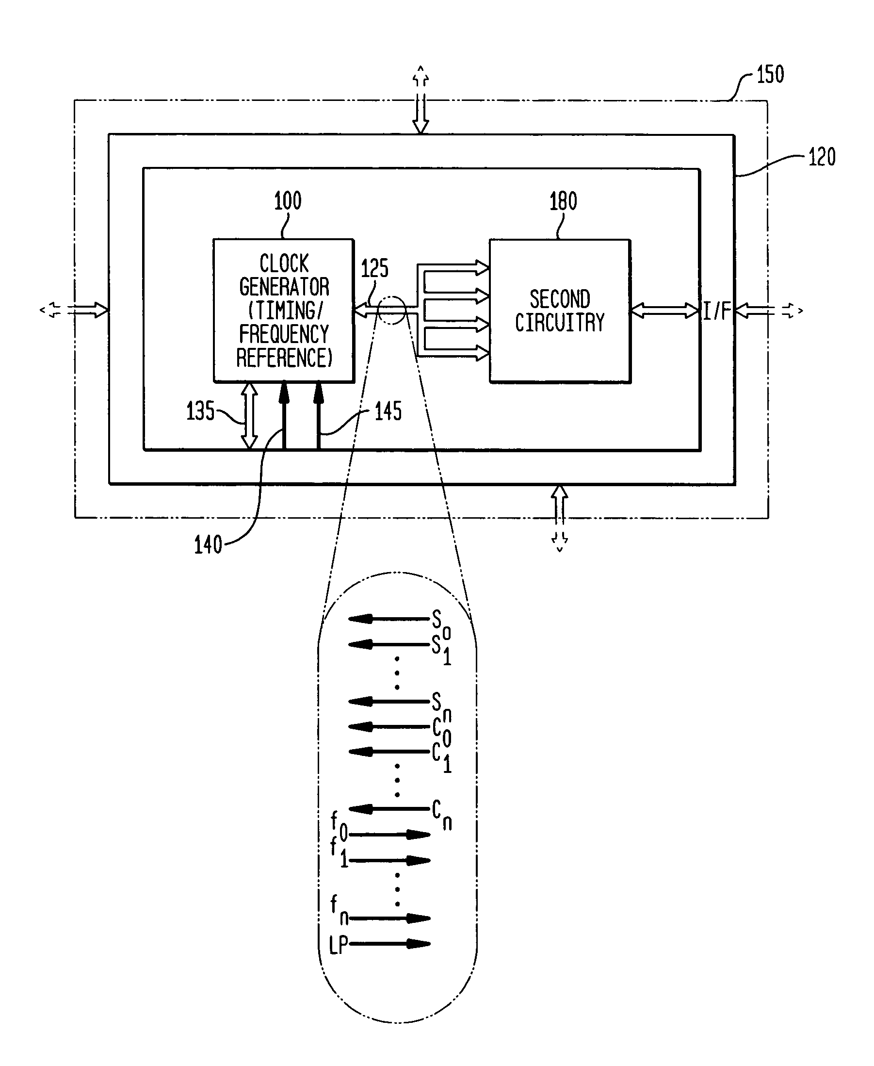
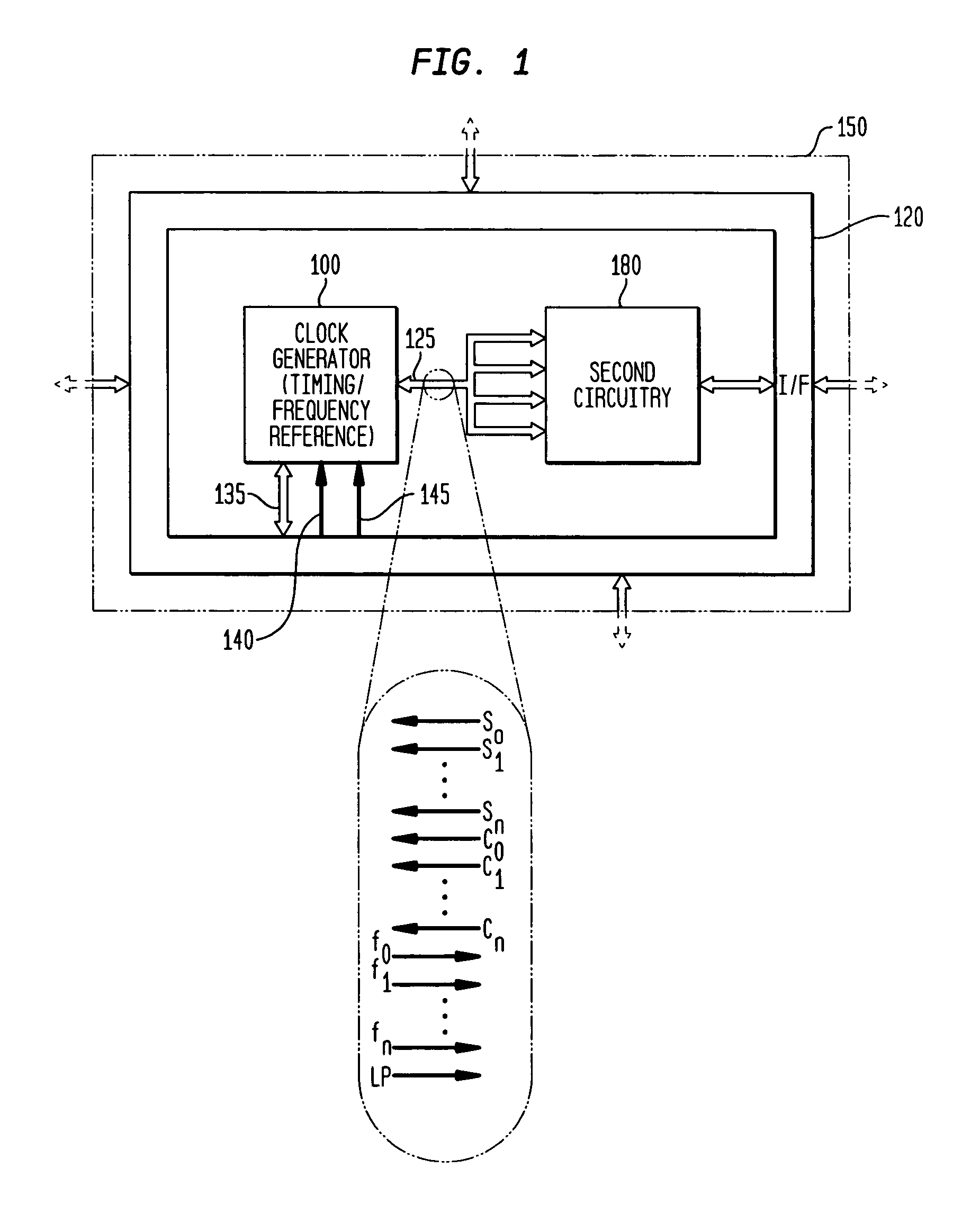
[0092] As indicated above, the various embodiments of the invention provide numerous advantages, including the ability to integrate a highly accurate (over PVT and age), low-jitter, free-running and self-referencing clock generator and / or a timing and frequency reference with other circuitry, such as illustrated in FIG. 1. FIG. 1 is a block diagram illustrating an exemplary system embodiment 150 in accordance with the teachings of the present invention. As illustrated in FIG. 1, the system 150 is a single integrated circuit, having a clock generator and / or timing / frequency reference 100 of the present invention integrated monolithically with other, or second, circuitry 180, together with interface (I / F) (or input / output (I / O) circuitry) 120. The interface 120 will generally provide power, such as from a power supply (not illustrated), ground, and other lines or busses to the clock generator 100, such as for calibration and frequency selection. As illustrated, one or more output cloc...
first embodiment
[0262] For example, the resonator typically comprises one or more inductors and capacitors, forming one or more LC-tanks or LC resonators. In a first embodiment, a double-balanced, differential LC oscillator topology is utilized. In other exemplary embodiments, differential or single-ended LC oscillator topologies may be utilized, for example, a single-ended Colpitts LC oscillator, a single-ended Hartley LC oscillator, a differential Colpitts LC oscillator (both common base and common collector versions), a differential Hartley LC oscillator (also both common base and common collector versions), a single-ended Pierce LC oscillator, a quadrature oscillator (e.g., formed from at least two double-balanced, differential LC oscillators), or an active inductor LC oscillator (which may be implemented to be either differential or single-ended) Additional LC oscillator topologies, now known or which become known, are considered equivalent and within the scope of the present invention.
[0263] ...
PUM
Abstract
In various embodiments, the invention provides a clock generator and/or a timing and frequency reference using an LC-oscillator topology, having a frequency controller to control and provide a stable resonant frequency, which is integrated with other, second circuitry such as a processor or controller. Frequency stability is provided over variations in a selected parameter such as temperature and fabrication process variations. The various apparatus embodiments include a sensor adapted to provide a signal in response to at least one parameter of a plurality of parameters; and a frequency controller adapted to modify the resonant frequency in response to the second signal. In exemplary embodiments, the sensor is implemented as a current source responsive to temperature fluctuations, and the frequency controller is implemented as a plurality of controlled reactance modules which are selectively couplable to the resonator or to one or more control voltages. The controlled reactance modules may include fixed or variable capacitances or inductances, and may be binary weighted. Arrays of resistive modules are also provided, to generate one or more control voltages.
Description
CROSS-REFERENCE TO RELATED APPLICATIONS [0001] This application is a continuation-in-part of and claims priority to McCorquodale, Michael S. et al., U.S. patent application Ser. No. 11 / 232,407, filed Sep. 20, 2005, entitled “Frequency Controller for a Monolithic Clock Generator and Timing / Frequency Reference”, which is a continuation-in-part of and claims priority to McCorquodale, Michael S. et al., U.S. patent application Ser. No. 11 / 084,962, filed Mar. 21, 2005, entitled “Monolithic Clock Generator and Timing / Frequency Reference”, which further claims priority to McCorquodale, Michael S. et al., U.S. Provisional Patent Application Ser. No. 60 / 555,193, filed Mar. 22, 2004, entitled “Monolithic and Top-Down Clock Synthesis with Micromachined Radio Frequency Reference”, which are commonly assigned herewith, the contents of all of which are incorporated herein by reference, and with priority claimed for all commonly disclosed subject matter. [0002] This application is also a continuat...
Claims
Application Information
Patent Timeline
Application Date:The date an application was filed.
Publication Date:The date a patent or application was officially published.
First Publication Date:The earliest publication date of a patent with the same application number.
Issue Date:Publication date of the patent grant document.
PCT Entry Date:The Entry date of PCT National Phase.
Estimated Expiry Date:The statutory expiry date of a patent right according to the Patent Law, and it is the longest term of protection that the patent right can achieve without the termination of the patent right due to other reasons(Term extension factor has been taken into account ).
Invalid Date:Actual expiry date is based on effective date or publication date of legal transaction data of invalid patent.