Method and system for laser cladding

a laser and cladding technology, applied in the field of laser cladding, can solve the problems of limiting engine combustion parameters, increasing the temperature of the valve in contact with such seats, and limiting the thermal conduction of the valv

Inactive Publication Date: 2006-07-13
GM GLOBAL TECH OPERATIONS LLC
View PDF11 Cites 19 Cited by
  • Summary
  • Abstract
  • Description
  • Claims
  • Application Information

AI Technical Summary

Problems solved by technology

Although such inserts enhance wear resistance beyond that of the parent aluminum, they may limit engine combustion parameters by restricting heat flow from the valves into the cylinder head and ultimately to the cooling jacket.
First, there can be gaps as large as 50-150 micrometers between the insert and parent support metal of the cylinder head; such gaps prevent efficient heat evacuation away from the seat through the head during combustion, consequently increasing the temperature of the valves in contact with such seats.
Secondly, inserts need to have a significant thickness to assure adequate rigidity during mechanical installation; such thickness contributes to thermal resistance, thus limiting thermal conduction from the valves.
As a consequence, the engine operating parameters are often varied to prevent extreme temperatures from being experienced by the valves, such as by restricting the degree of spark advance and or compression ratio, thereby limiting the available horsepower and torque.
In addition, the significant thickness of the valve seat insert limits the size of the valve, thereby limiting the available horsepower and torque.
However, laser cladding introduces a significant amount of heat into the seat supporting region which can significantly modify the metallurgy of the underlying aluminum alloy of the cylinder head.
For example, when a single power laser setting is used for cladding a valve seat, the result of the dilution between the two materials is not uniform.
This non-uniformity is caused by the variable material thickness surrounding the valve seat due to the presence of cooling jackets, a spark plug hole, and a general varying configuration of the cylinder head proximate the valve seat.
This variation in dilution is not desirable around the valve seat, which can lead to premature cracking.
When an amount of heat input from the laser is lacking, the copper alloy powder is not melted sufficiently into the aluminum base metal.

Method used


Image

  • Method and system for laser cladding
  • Method and system for laser cladding
  • Method and system for laser cladding

Examples


Embodiment Construction

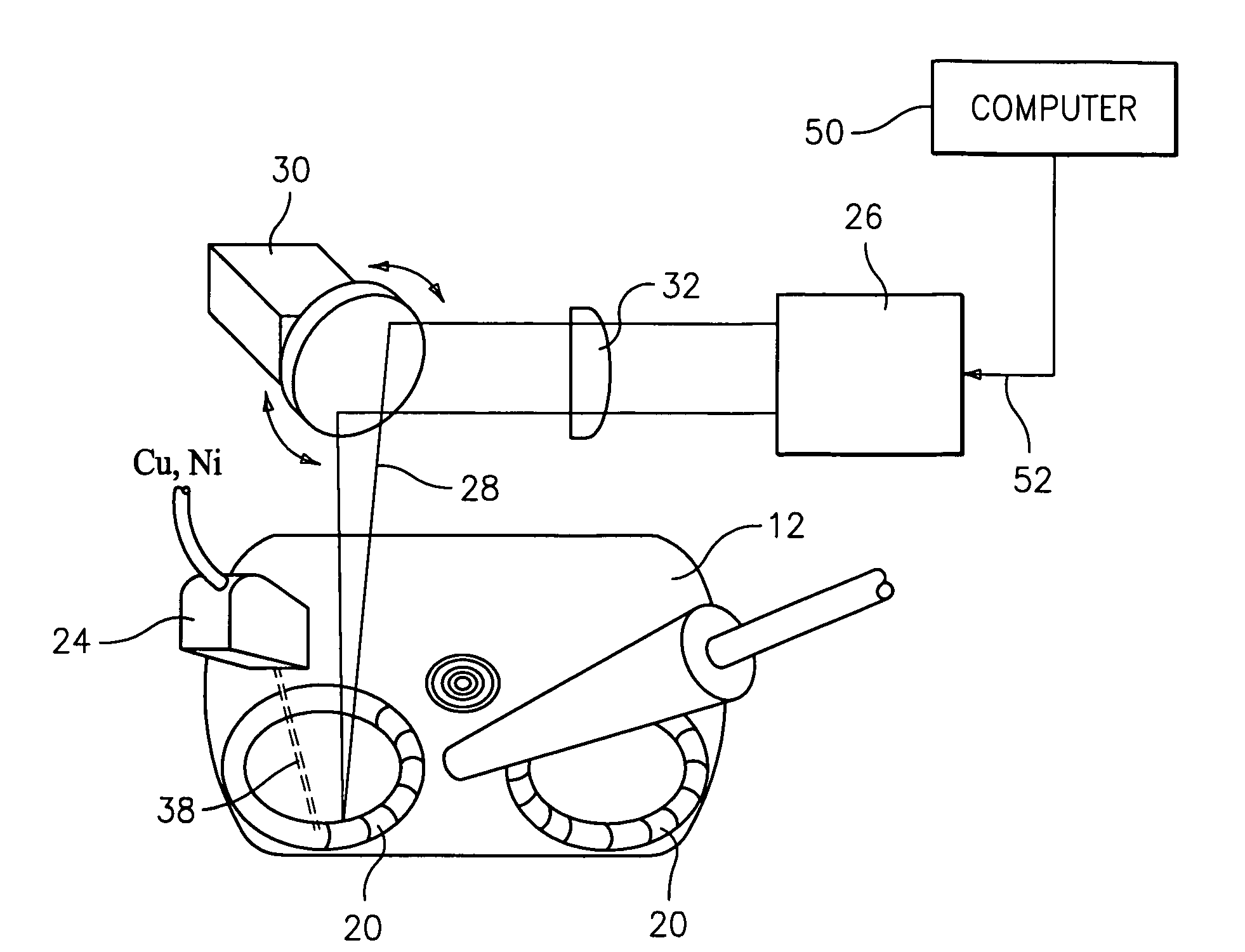
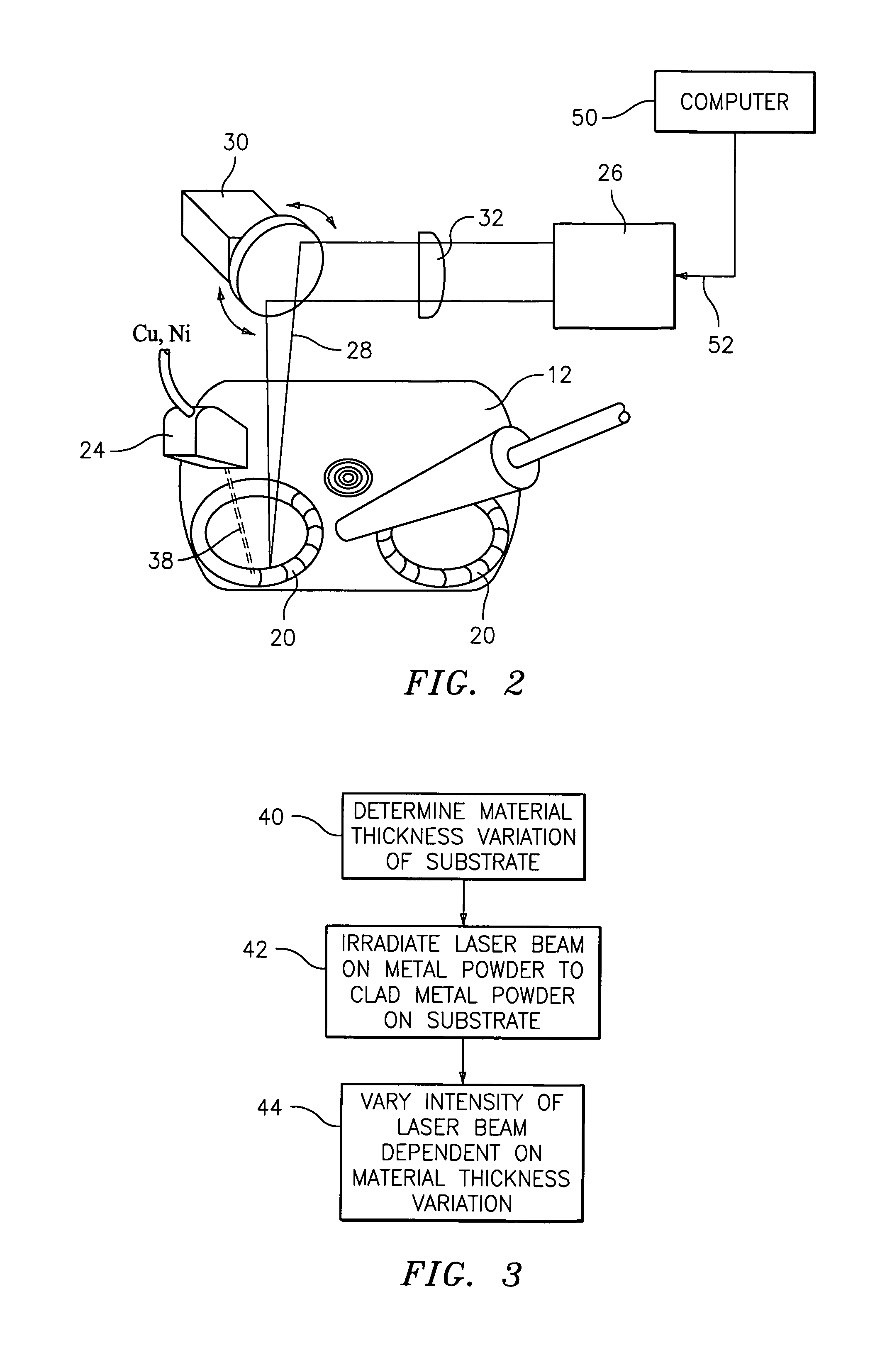
[0021] As used herein, the phrase “laser cladding process” means the laser powder or metal mixture deposition process in which material of a single layer or multiple layers is deposited on a substrate by melting the metal mixture and substrate by a laser to dilute the materials together. The phrase “clad” refers to the deposited layer on the substrate. The process of making clads is called “cladding” and synonymously “coating” when the thickness of the clad is small and the process is used to coat or dilute a surface of the substrate with another material.

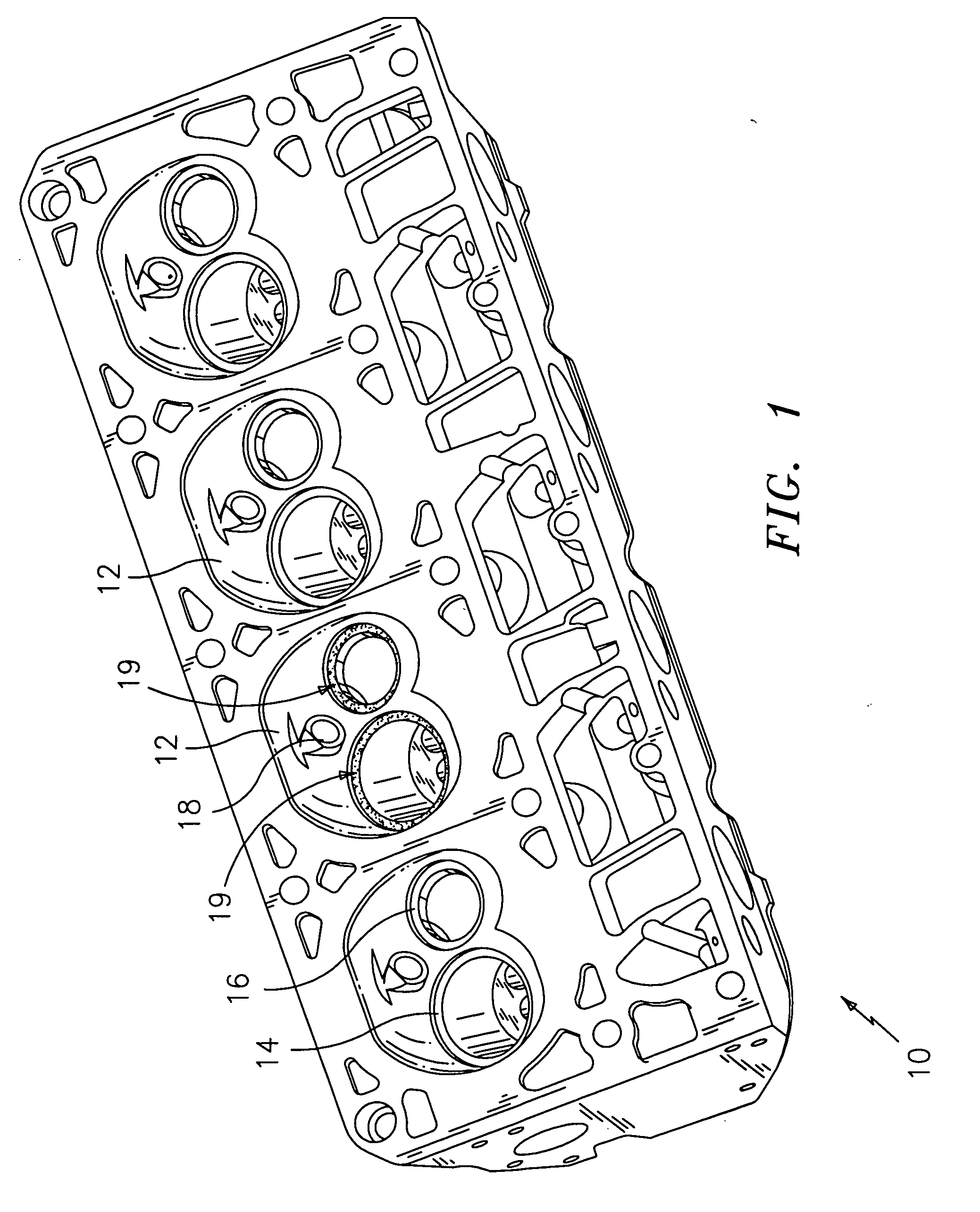
[0022]FIG. 1 illustrates an engine cylinder head assembly 10 with four combustion chambers 12 formed therewith. Each chamber 12 shows pre-machined pockets for the cladding deposition of an intake valve seat 14 and an exhaust valve seat 16 with an aperture 18 for threadably receiving a spark plug (not shown). Engine head assembly 10, as illustrated, is an aluminum-based head; however, other metal and metal alloy base materials are ...


PUM

PropertyMeasurementUnit
widthaaaaaaaaaa
temperatureaaaaaaaaaa
thickaaaaaaaaaa

Abstract

A method and system for laser cladding includes determining a material thickness variation of a substrate, and varying laser intensity dependent on the determination of the material thickness variation of the substrate. The determination of the material thickness variation of the substrate includes calculating parameters indicative of a relative material thickness between a first target position and a second target position.

Description

BACKGROUND [0001] The present disclosure relates generally to a method for laser cladding, and more particularly, to a method for manufacturing a valve seat using a laser cladding process. [0002] In internal combustion engines, aluminum or aluminum alloys are frequently employed as materials for a number of the major engine castings such as the cylinder heads. When the cylinder heads are formed from aluminum or aluminum alloys, however, certain components of the cylinder head are formed from a dissimilar material so as to improve durability of the engine. For example, valve seats are provided where the valve face of an intake or exhaust valve engages the cylinder head body. Since the valve seat engages the intake or exhaust valve repeatedly and is subject to high temperature, the valve seat is formed from a harder material such as iron or ferrous iron alloys to extend the valve seat life. [0003] Valve seat inserts for aluminum alloy engine heads have been used for some time to reinf...

Claims


Application Information

Patent Timeline
Patent Type & Authority Applications(United States)
IPC IPC(8): C23C14/30C23C16/52B05C11/00
CPCB23K26/34C23C24/106B05B7/228B05B12/084B23K26/0626B23K26/3206B23K35/0244F01L3/02F01L2101/00F01L2103/00F01L2820/01B23K2203/10B23K26/3226B23K26/32B23K2103/08B23K2103/10B23K2103/12B23K2103/18B23K2103/50F01L2301/00F01L2303/00
Inventor STANEK, JENNIFER M.NEAL, TIMOTHY L.SANTANAM, CHANDRAN B.WU, KO-JEN
Owner GM GLOBAL TECH OPERATIONS LLC
Why Eureka
Try Eureka