Microscope and observation method

a microscope and observation method technology, applied in the field of microscopes and observation methods, can solve the problems of spatial resolution limitation of a general microscope, inability to increase spatial resolution beyond a certain level, etc., and achieve the effect of improving spatial resolution

Inactive Publication Date: 2012-12-06
OSAKA UNIV
View PDF1 Cites 17 Cited by
  • Summary
  • Abstract
  • Description
  • Claims
  • Application Information

AI Technical Summary

Benefits of technology

[0021]According to the present invention, it is possible to provide a microscope and an observation method which can improve a spatial resolution.

Problems solved by technology

A spatial resolution of a general microscope is limited by diffraction limit.
Thus, existing microscopes have a problem that once a light wavelength and a numeric aperture are determined, the spatial resolution cannot be increased beyond a certain level.

Method used


Image

  • Microscope and observation method
  • Microscope and observation method
  • Microscope and observation method

Examples


first embodiment

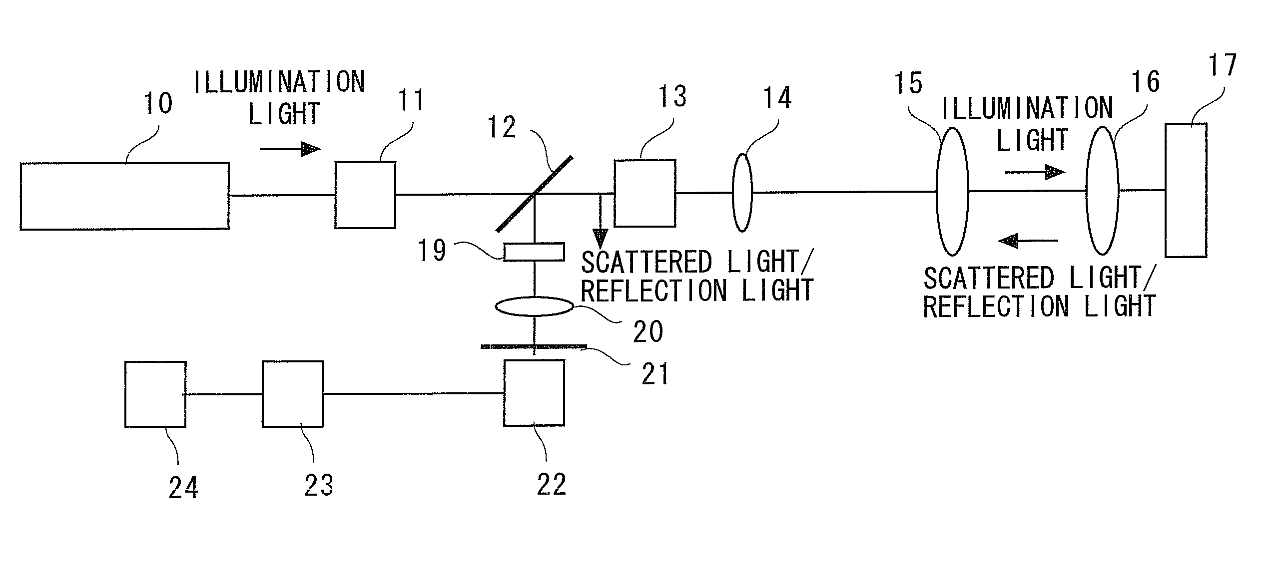
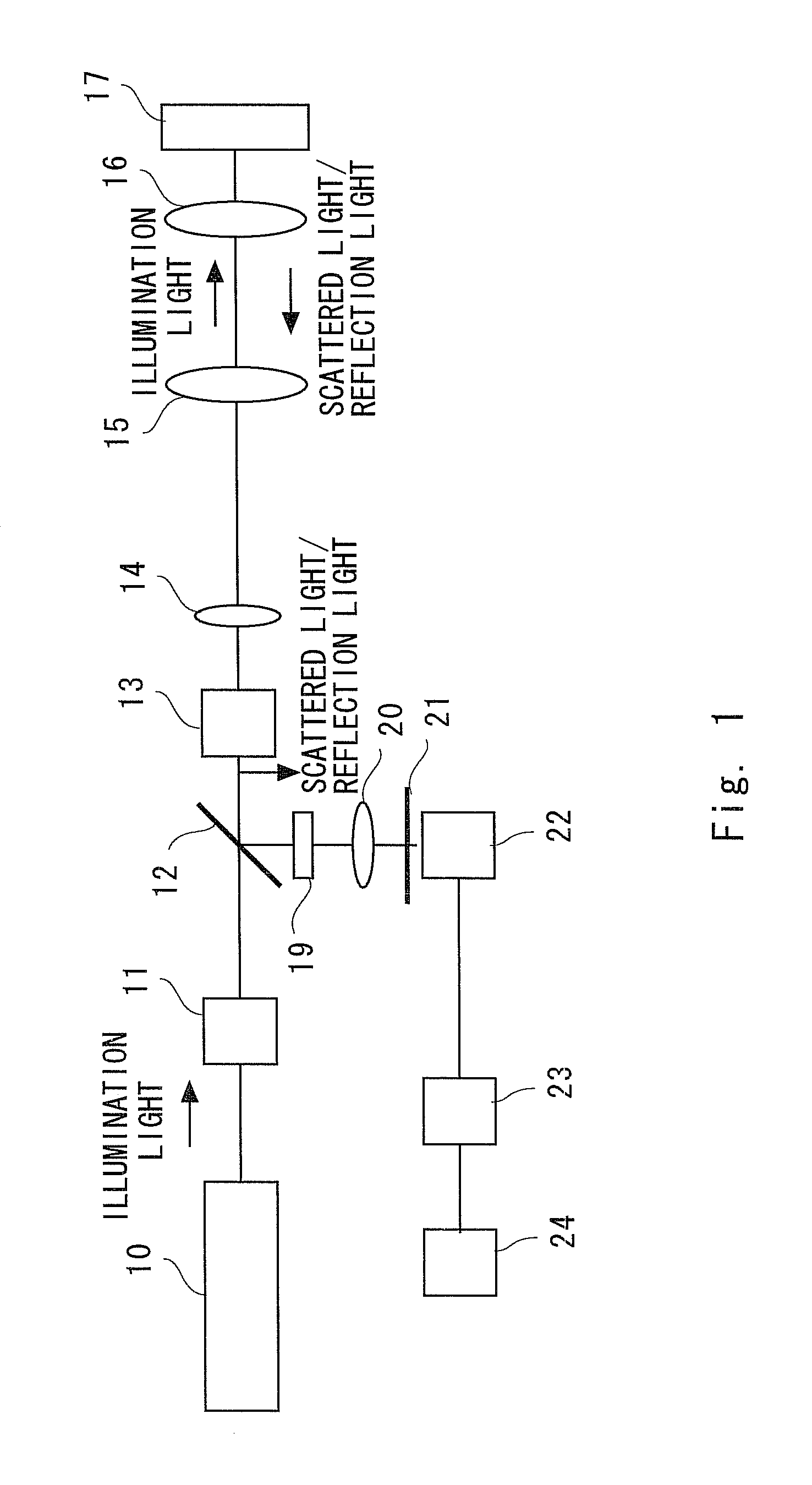
[0049]In this embodiment, a spatial resolution is improved by utilizing saturation of reflection light, scattered light, or transmitted light. That is, an observation of saturation components of reflection light, transmitted light, or scattered light improves a spatial resolution. A laser microscope according to a first embodiment of the present invention is a confocal microscope, in other words, a laser scanning type microscope. This laser microscope is described with reference to FIG. 1. FIG. 1 is a diagram schematically showing the configuration of the laser microscope according to the present invention. Reference numeral 10 denotes a light source; 11, a modulator; 12, a beam splitter; 13, a scanner; 14, a lens; 15, a lens; 16, an objective lens; 19, a filter; 20, a lens; 21, a pinhole; 22, a detector; 23, a lock-in amplifier; and 24, a processing apparatus. The laser microscope shown in FIG. 1 detects reflection light (or scattered light).

[0050]The light source 10 is a laser lig...

second embodiment

[0086]In this embodiment, observation is performed based on saturation components of signal light generated due to a nonlinear optical effect. For example, scattered light or the like generated in a sample due to the nonlinear optical effect is detected. In this case, scattered light having a wavelength different from a laser wavelength is detected. For example, various types of light generated by hyper-Rayleigh scattering, harmonic generation, Raman scattering, coherent anti-Stokes Raman scattering (CARS), four-wave mixing, stimulated emission, difference frequency generation, sum frequency generation, parametric fluorescence, or stimulated Raman scattering (SRS), for example, may be detected. The scattered light includes scattered light generated due to the nonlinear optical effect. The generation of the nonlinear optical effect or other optical effects causes a loss in light intensity, that is, a harmonic loss. The term “harmonic loss” herein described refers to a harmonic loss i...

example

[0132]FIGS. 14 to 17 show the actual measurement results. FIG. 14 is a graph showing nonlinear reflection characteristics of a metal thin-film surface. In the measurement shown in FIG. 14, the laser wavelength was set to 780 nm. FIG. 15 is a graph showing nonlinear reflection characteristics of an LBO crystal surface. In the measurement shown in FIG. 15, the laser wavelength was set to 780 nm. FIG. 16 is a graph showing nonlinear scattering characteristics from gold fine particles.

[0133]In the measurement shown in FIG. 16, the laser wavelength was set to 520 nm, and gold fine particles having a diameter of 50 nm were used. FIG. 17 is a graph showing saturation characteristics of CARS light from L-Alanine. In the measurement shown in FIG. 17, the wavelength of Stokes light was set to 820 nm and the wavelength of pump light was set to 785 nm. Further, the Stokes light intensity was set to 3100 kW / cm2 to be kept constant, and the pump light was modulated.

[0134]As shown in FIGS. 14 to 1...


PUM

PropertyMeasurementUnit
frequencyaaaaaaaaaa
frequencyaaaaaaaaaa
frequencyaaaaaaaaaa

Abstract

Provided is a microscope and an observation method which can improve spatial resolution. A microscope according to an aspect of the invention includes a laser light source (10), an objective lens (16) that focuses light from the laser light source on a sample, and a detector (22) that detects the laser light as signal light from a sample (17) when the sample (17) is irradiated with the laser light. The light is applied to the sample with an intensity changed to obtain a nonlinear region where intensities of the light and the signal light have a nonlinear relation due to occurrence of saturation or nonlinear increase of the signal light when the light has a maximum intensity, and the detector (22) detects the signal light according to the intensity of the laser light to perform observation based on a saturation component or a nonlinear increase component of the signal light.

Description

TECHNICAL FIELD[0001]The present invention relates to a microscope and an observation method.BACKGROUND ART[0002]A spatial resolution of a general microscope is limited by diffraction limit. Thus, existing microscopes have a problem that once a light wavelength and a numeric aperture are determined, the spatial resolution cannot be increased beyond a certain level.[0003]The inventors of this application have proposed a fluorescence microscope to improve the spatial resolution (Patent Literature 1). In this fluorescence microscope, observation is performed based on saturation components of fluorescence.CITATION LISTPatent Literature[0004][Patent Literature 1] International Patent Publication No. WO 2006 / 061947SUMMARY OF INVENTIONTechnical Problem[0005]However, the fluorescence microscope described above has a problem that the spatial resolution for components other than fluorescence cannot be improved.[0006]The present invention has been accomplished in view of the above-mentioned pr...

Claims


Application Information

Patent Timeline
Patent Type & Authority Applications(United States)
IPC IPC(8): G02B21/14G01J3/44G01N21/59G01N21/17G01N21/47G01J3/50
CPCG01N2021/653G02B2207/114G02B21/002G01N2021/655
Inventor FUJITA, KATSUMASAKAWANO, SHOGOYAMANAKA, MASAHITOKAWATA, SATOSHI
Owner OSAKA UNIV
Why Eureka
Try Eureka