
Burner for a reformer of a fuel cell system, and reformer and fuel cell system with the same

a fuel cell and burner technology, applied in the field of fuel cell systems, can solve the problems of power loss, parasitic power consumption of heating apparatus, and decrease of overall system performance and energy efficiency, and achieve the effect of reducing the reaction initiation time of an oxidation catalyst and reducing the power consumption necessary

Inactive Publication Date: 2006-07-13
SAMSUNG SDI CO LTD
View PDF32 Cites 12 Cited by
  • Summary
  • Abstract
  • Description
  • Claims
  • Application Information

AI Technical Summary

Benefits of technology

[0014] In one embodiment, a burner for a reformer of a fuel cell is provided which can reduce the reaction initiation time of an oxidation catalyst for the burner assembly, and reduce the power consumption necessary for maintaining a reaction initiation temperature range of the oxidation catalyst.

Problems solved by technology

However, when the conventional reformer begins operating, it maintains a initial reaction temperature for the oxidation catalyst by providing a thermal resource, with a predetermined temperature range, to the reactor body of the burner assembly using a separate heating apparatus, which causes power loss due to the heating of the overall reactor body up to the reaction temperature range.
Since the fuel system is driven using electric power generated by the stack (parasitic power), the parasitic power consumed by the heating apparatus increases.
Accordingly, the performance and energy efficiency of the overall system decrease.
In addition, since the reformer heats the reactor body to maintain the reaction initiation temperature of the oxidation catalyst, the initiation time of the reaction of the oxidation catalyst is delayed, and thereby, the heat efficiency and the performance of the reformer are lowered.

Method used


Image

  • Burner for a reformer of a fuel cell system, and reformer and fuel cell system with the same
  • Burner for a reformer of a fuel cell system, and reformer and fuel cell system with the same
  • Burner for a reformer of a fuel cell system, and reformer and fuel cell system with the same

Examples


Embodiment Construction

[0033] Reference will now be made in detail to the embodiments of the invention, examples of which are illustrated in the accompanying drawings. The embodiments are described below to explain the invention by referring to the figures.

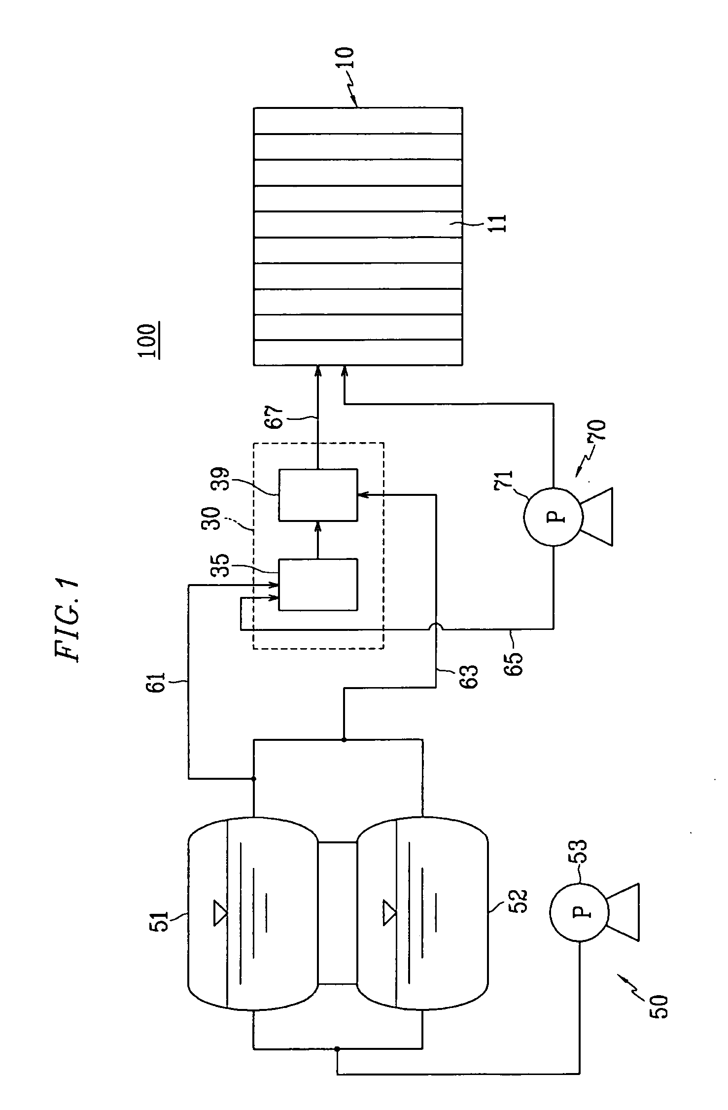
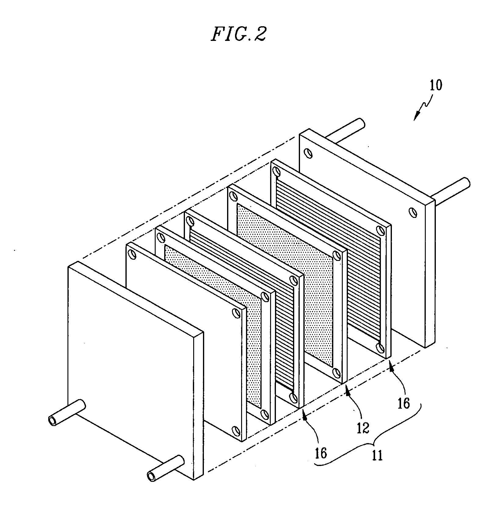
[0034]FIG. 1 is an overall schematic view of a fuel cell system according to an embodiment of the present invention, and FIG. 2 is an exploded perspective view of a stack of FIG. 1.

[0035] Referring to one embodiment shown in the drawings, in the fuel system 100 according to the invention, a polymer electrode membrane fuel cell (PEMFC) method is used in which hydrogen is generated by reforming fuel containing hydrogen, and electrical energy is generated by the electrochemical reaction of the hydrogen and oxidant gas.

[0036] In the fuel system 100, fuel for generating electricity is taken to include liquid or gas fuel containing hydrogen such as methanol, ethanol, or natural gas. In the following embodiments, the fuel used is understood to be in liquid ...


PUM

PropertyMeasurementUnit
Poweraaaaaaaaaa
Compositionaaaaaaaaaa
Structureaaaaaaaaaa

Abstract

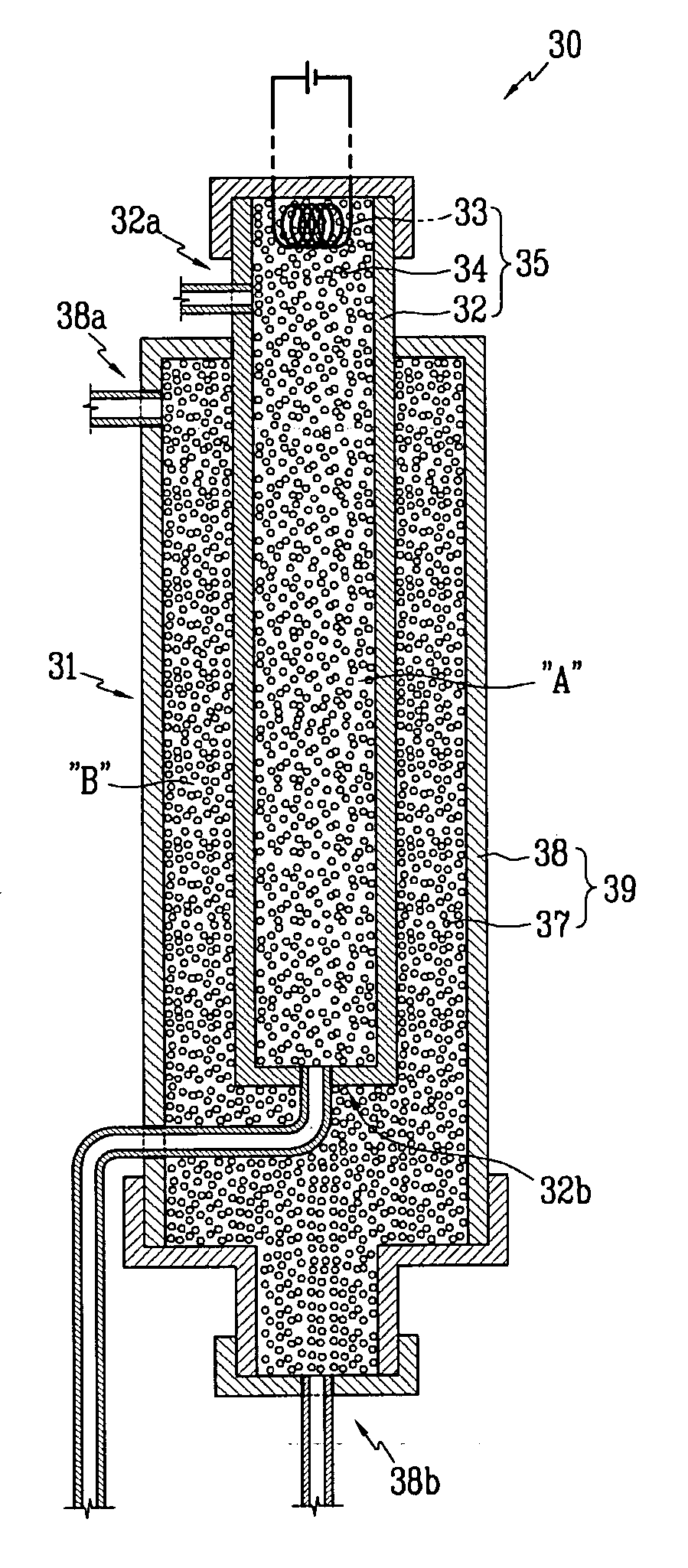
A burner for a reformer of a fuel cell system includes a body having a catalyst inside thereof; and a heating member partially embedded within the catalyst to provide an auxiliary thermal source to the catalyst.

Description

CROSS-REFERENCE TO RELATED APPLICATION [0001] This application claims priority to and the benefit of Korean Patent Application No. 10-2005-0002119 filed in the Korean Intellectual Property Office on Jan. 10, 2005, the entire content of which is incorporated herein by reference. BACKGROUND OF THE INVENTION [0002] 1. Field of the Invention [0003] The present invention relates to a fuel cell system and, more particularly, to the structure of burners for the reformer of a fuel cell system. [0004] 2. Description of the Related Art [0005] A fuel cell is a system for producing electric power. In a fuel cell, chemical reaction energy between oxygen and hydrogen contained in hydrocarbon-group materials such as methanol, ethanol, and natural gas is directly converted into electric energy. [0006] Depending on the type of electrolyte used, the fuel cell is classified into different types including a phosphate fuel cell, molten carbonate fuel cell, solid oxide fuel cell, and polymer electrolyte ...

Claims


Application Information

Patent Timeline
IPC IPC(8): H01M8/06F23D14/18B01J8/02
CPCB01J8/025B01J8/0257B01J8/0285B01J2208/00309B01J2208/00504C01B3/323C01B3/384C01B2203/0233C01B2203/0238C01B2203/0261C01B2203/066C01B2203/0811C01B2203/1058C01B2203/107C01B2203/1076C01B2203/1223C01B2203/1229C01B2203/1241C01B2203/1276C01B2203/142C01B2203/1604C01B2203/1614C01B2203/1685C01B2203/82H01M8/0618Y02E60/50Y02P20/129Y02P20/141B28D1/30B28D1/18B28D7/04
Inventor KIM, JU-YONGPARK, ZINSON, IN-HYUK
Owner SAMSUNG SDI CO LTD
Learn More