Structural element, method for manufacturing a structural element and use of a structural element for an aircraft hull

a technology of structural elements and aircraft hulls, applied in the direction of fuselages, transportation and packaging, building repairs, etc., can solve the problems of reducing the life of reinforcing elements, cracks also propagating in reinforcing elements, and affecting the service life of structural elements, etc., to achieve reliable and secure attachment, reduce cracks, and reduce the effect of crack growth

Inactive Publication Date: 2006-07-20
AIRBUS OPERATIONS GMBH
View PDF40 Cites 7 Cited by
  • Summary
  • Abstract
  • Description
  • Claims
  • Application Information

AI Technical Summary

Benefits of technology

[0027] According to yet still a further embodiment, the reinforcing element and the sheathing element are made out of different materials. This may enable a mutually independent optimization of the respective partial tasks of the reinforcing element and sheathing element, since the different materials may be selectively chosen to reflect the corresponding tasks. According to another embodiment, the sheathing element includes a polymeric material such as plastic, for example. The sheathing element may include an organic material. As an alternative, the sheathing element may comprise or consist of a metal alloy. According to still another embodiment, the sheathing element comprises completely or partially, fibers. Such fibers may be especially advantageous for suppressing crack growth. In one example, the fibers may have a length of at least 20 mm. According to yet another embodiment, the fibers provided run unidirectionally, e.g., in the direction of the reinforcing element, and/or be aligned in the directi

Problems solved by technology

In addition, the structures fabricated through welding are mostly comparatively cost-effective to manufacture.
Given an integral design (such as a welded or milled brace), there is a danger that the crack will also propagate in the reinforcing element.
This effect reduces the life of the reinforcing elements, and diminishes the damage tolerant properties of integral structures.
However, these measures

Method used


Image

  • Structural element, method for manufacturing a structural element and use of a structural element for an aircraft hull
  • Structural element, method for manufacturing a structural element and use of a structural element for an aircraft hull
  • Structural element, method for manufacturing a structural element and use of a structural element for an aircraft hull

Examples


first embodiment

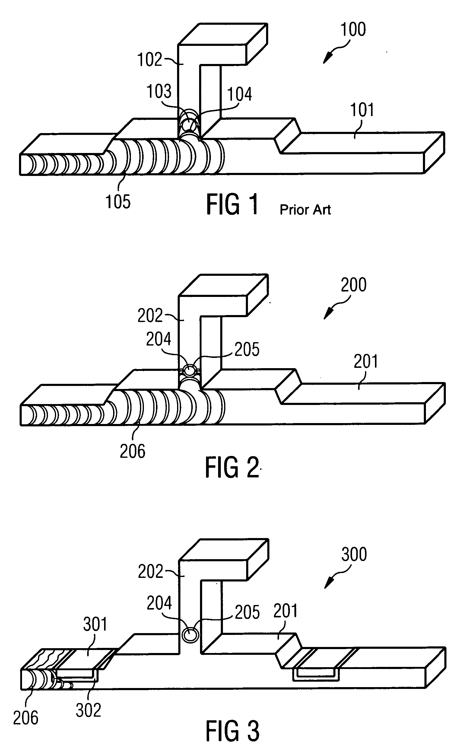
[0031]FIG. 2 is a structural element according to a

[0032]FIG. 3 is a structural element according to another embodiment.

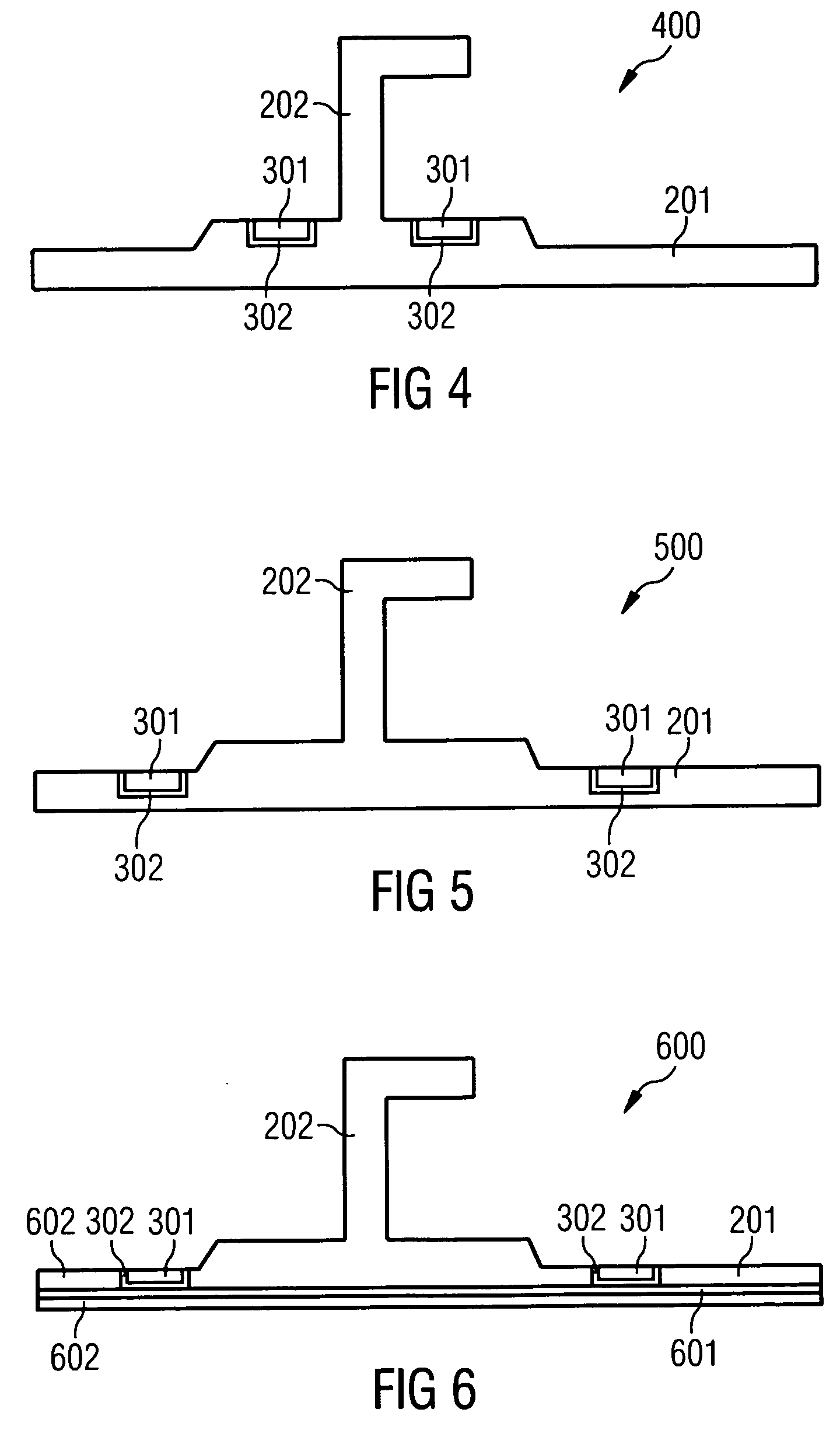
[0033]FIG. 4 is a structural element according to another embodiment.

[0034]FIG. 5 is a structural element according to another embodiment.

[0035]FIG. 6 is a structural element according to another embodiment.

[0036]FIG. 7 is a structural element according to another embodiment.

[0037]FIG. 8 is a structural element according to another embodiment.

[0038]FIG. 9 is a structural element according to another embodiment.

DETAILED DESCRIPTION OF PREFERRED EMBODIMENTS

[0039] The depictions in the figures are diagrammatic, and not to scale.

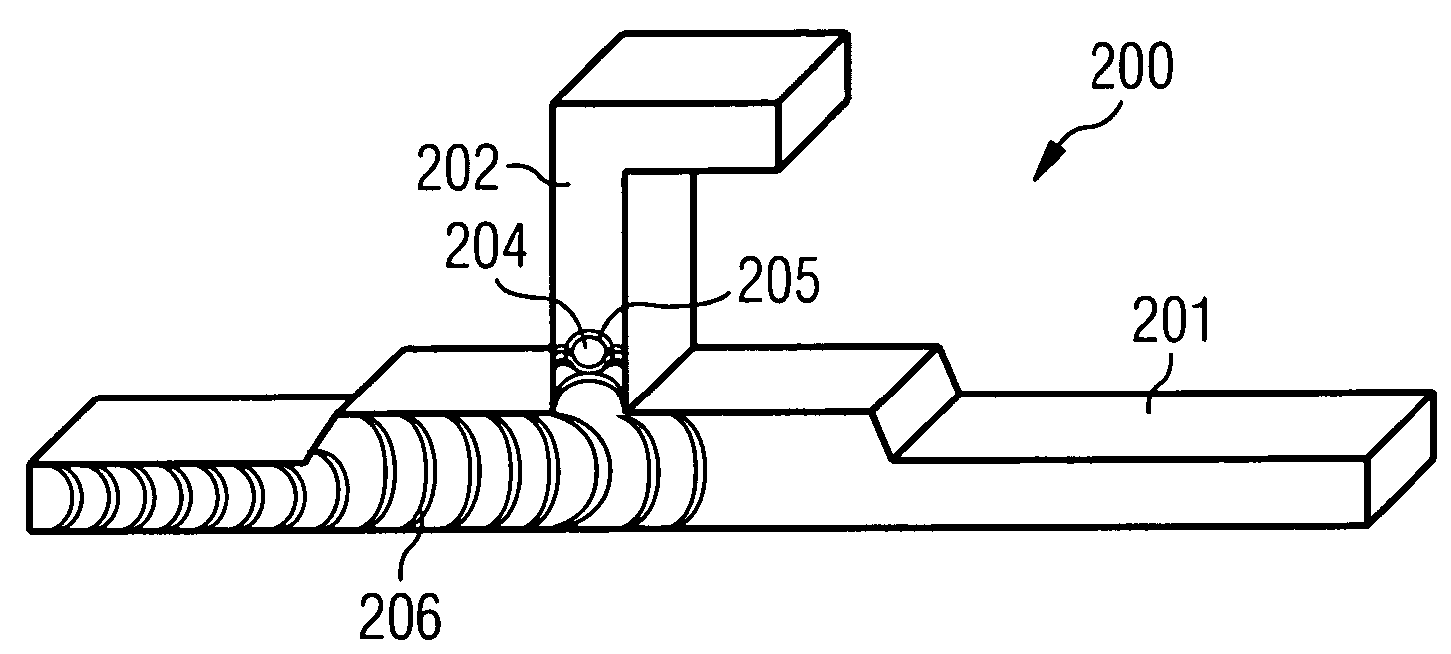
[0040] Now, referring to the embodiment illustrated in FIG. 2, a structural element 200 contains a skin panel 201, a stringer element 202 integrally provided with the skin panel 201 (as a bracing element for bracing the skin panel 201), and a reinforcing element 204 enveloped by a sheathing element 205. The reinforcing element 204 is en...

second embodiment

[0042] Now, reference will be made to FIG. 3 in describing a structural element 300 according to one embodiment of the invention. In addition to providing the reinforcing element 204 enveloped by the sheathing element 205 in the stringer element 202, the structural element 300 integrates an additional reinforcing element 301 in the skin panel 201. The additional reinforcing element 301 is enveloped by an additional sheathing element 302, wherein the reinforcing element 301 may be similarly designed as the reinforcing element 304 in terms of material, and the sheathing element 302 may be made out of the same material as the sheathing element 205. Providing the reinforcing element 301 enveloped by the sheathing element 302 in the skin panel 201 as well may allow for further avoidance of crack propagation 206 even more efficiently, and thereby additionally increase the damage tolerance of the structural element 300.

third embodiment

[0043] In FIG. 4, a structural element 400 according to the invention is similar to the structural element 300, but contains no reinforcing element 204 enveloped by a sheathing element 205 in the stringer element 202.


PUM


Abstract

A structural element includes the following elements: a carrier element, a reinforcing element, and a sheathing element. At least a portion of the reinforcing element is enveloped by the sheathing element and the reinforcing element is embedded in the carrier element. Materials of the elements are selected to inhibit crack initiation or propagation in the elements and/or from one element to another. An intermediate layer of a different material may be added between elements to further inhibit crack initiation and propagation and to inhibit corrosion, such as galvanic corrosion.

Description

RELATED APPLICATIONS [0001] This application claims the benefit of the filing date of U.S. Provisional Patent Application No. 60 / 632,091 filed Dec. 1, 2004, and of German Patent Application No. 10 2004 058 014.6 filed Dec. 1, 2004, the disclosures of which are hereby incorporated herein by reference.FIELD OF ONE EMBODIMENT OF THE INVENTION [0002] The field relates to a structural element, a method for manufacturing a structural element and use of a structural element for an aircraft hull. TECHNOLOGICAL BACKGROUND [0003] Light structural elements of the kind also used in particular in the aerospace industry often consist of an outer skin reinforced on the inside by a two-dimensional bracing. For example, an aircraft fuselage with an outer skin reinforced by stringers and frames is assembled in this way. Special emphasis is placed on reducing the weight during the design of such light structural elements, however the light structural elements shall satisfy varying strength, fatigue an...

Claims


Application Information

Patent Timeline
IPC IPC(8): E04C1/00
CPCB64C1/06B64C1/12Y10T428/24174Y02T50/42B64C2001/0081Y02T50/40
Inventor VICHNIAKOV, ALEXEI
Owner AIRBUS OPERATIONS GMBH
Why Eureka
Try Eureka