Air cleaner

a technology of air cleaning and air filter, which is applied in the direction of chemical/physical/physical-chemical processes, energy-based chemical/physical/physical-chemical processes, separation processes, etc., can solve the problems of ineffective improvement of air quality of air filtered by air cleaning devices in which active carbon has not been replaced, the time and chance of air contact with the photocatalyst is greatly increased, and the purification efficiency of air cleaning devices is further increased.

Inactive Publication Date: 2006-07-20
CHIAPHUA INDS
View PDF6 Cites 25 Cited by
  • Summary
  • Abstract
  • Description
  • Claims
  • Application Information

AI Technical Summary

Benefits of technology

[0005] The present invention has been made to overcome one or more aspects of the above disadvantages in the prior arts. Accordingly, it is an object of the present invention to provide an air cleaning device using photocatalyst in which the chance and time for which the air contacts with the catalyst and the catalytical effect are effectively enhanced and the air purifying efficiency of the catalyst reaction is remarkably increased.
[0015] According to the present invention, a photocatalyst reaction unit in which an elongated air duct is combined with an air inlet port disposed in a tangential direction of the air duct and spiral guide blades disposed at the air inlet port thereof is employed. The air drawn into the air duct through the blower flows spirally inside the air duct along the interior wall of the air duct. As a result, the time and chance for which the air contacts with the photocatalyst are greatly increased.
[0016] With this construction, ultra violet ray emitted from the ultra violet ray tube can be directly incident onto the photocatalyst without blocking so that the catalyst reaction effect is greatly enhanced. Thus, the purifying efficiency of the air cleaning device is further increased. Particularly, since the specific gravity of the volatile organic chemical (VOC) and bacteria is greater than that of the air, the volatile organic chemical (VOC) and bacteria will be certainly thrown against the interior wall of the air duct when the air rotates around the central axis of the air duct due to the eccentric forces applied thereupon. In this way, the volatile organic chemical (VOC) and bacteria will come more closely to the photocatalyst. Consequently, the photocatalyst causes the volatile organic chemical (VOC) and bacteria to be decomposed into free ion radicals so that the effects of sterilization, deodorization and purification of air can be achieved.
[0017] Particularly, it is preferably employed that the air outlet port and the air inlet port are disposed at the same end. When the air rotationally flows from the air inlet port to the distal end of the air duct, the air returns back to air inlet port end along the central portion of the air current (i.e. the position where the ultra violet ray tubes are located) so as to be discharged from the vent opening due to vortex effect of air current (the center of the spiral air current where the pressure is smallest corresponds to the central axis of the air duct i.e. the position adjacent to where the ultra violet ray tubes are located). Thus, the time and chance for performing sterilization by the ultra violet ray tubes are increased.
[0018] Moreover, due to generation of the central air current, the air drawn into the air duct is forced toward to the interior wall of the air duct so that the time and chance for which the air contacts with the photocatalyst are increased. As a result, the purifying efficiency of the air cleaning device is further enhanced.
[0019] The air cleaning device of the present invention has a simple construction and can be easily effected with good applicability. The air cleaning device according to the present invention can be widely used as a purifying device in rooms inside a house, automobiles or a good variety of appliances such as air conditioners and dishwashers for dust-removing, sterilization, and air-cleaning.

Problems solved by technology

However, the above conventional air cleaning device is problematic in that the active carbon must be replaced when it is saturated with contaminants removed from the air.
More often than not, the consumer may neglect to replace the active carbon.
Accordingly, air filtered by the air cleaning device in which the active carbon has not been replaced is not effectively improved in quality.
However, the above two kinds of conventional air cleaning device have the following disadvantages.
For the former one, it is disadvantageous in complicated structure and high cost.
As a result, no commercialized product of the above air cleaning device is available till now.
However, as the carrier of the catalyst of the air cleaning device is configured to be a web-layering shape, the light is not evenly incident on the catalyst.
Further, the time in which the air contacts with the catalyst is short and the chance for the contact is relatively low.
As a result, the purifying efficiency of the photocatalyst is not satisfactory.

Method used


Image

  • Air cleaner
  • Air cleaner
  • Air cleaner

Examples


Embodiment Construction

[0025] A preferred embodiment of the present invention will be described hereinafter in detail with reference to the attached drawings, wherein the like reference numerals refer to the like elements throughout the specification. The present invention may, however, be embodied in many different forms and should not be construed as being limited to the embodiment set forth herein; rather, this embodiment is provided so that the present disclosure will be thorough and complete, and will fully convey the concept of the invention to those skilled in the art.

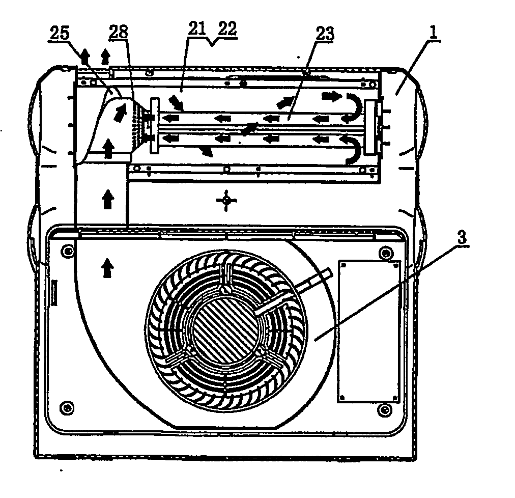
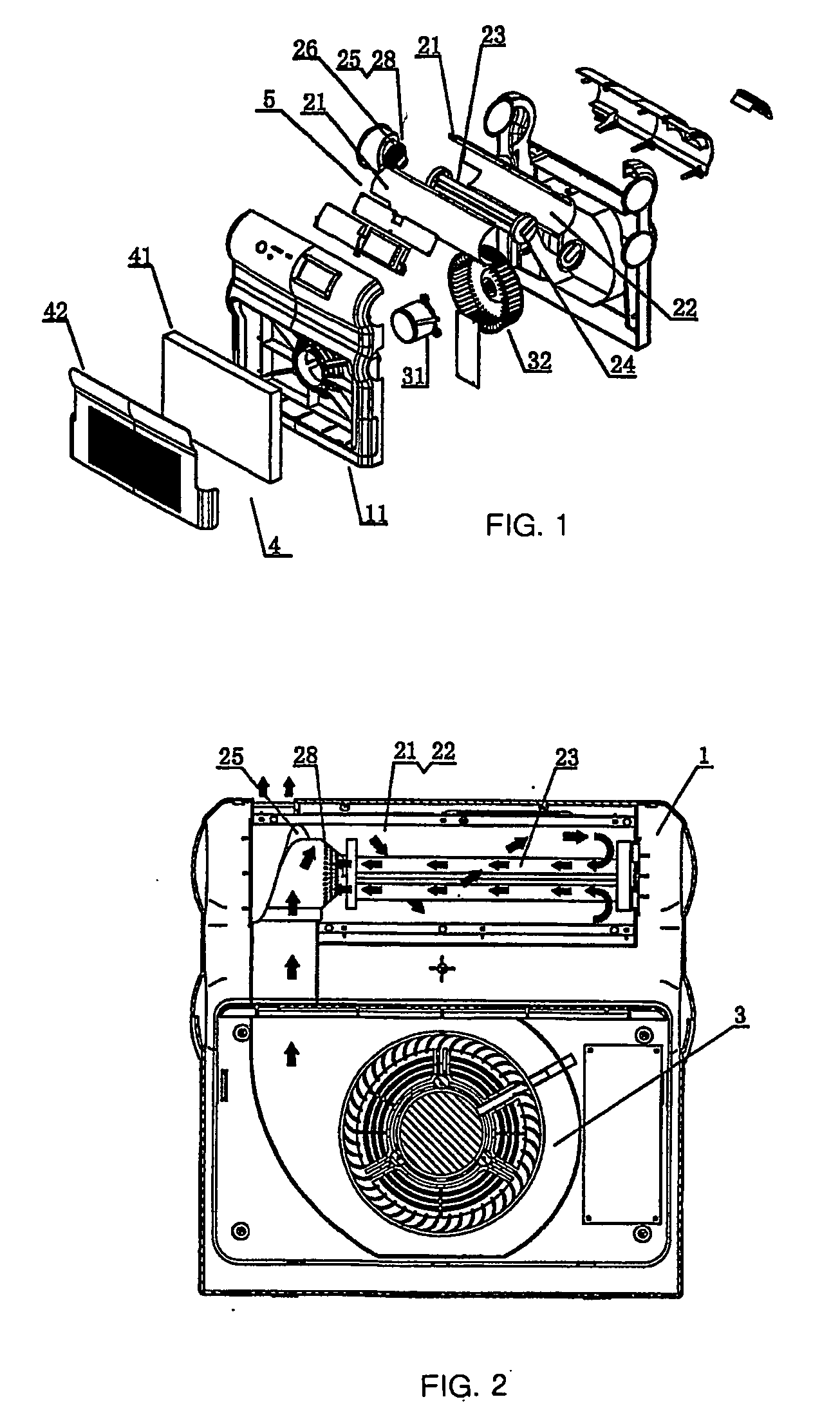
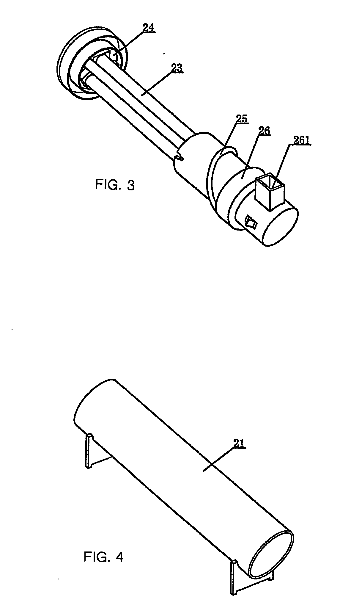
[0026] As shown in FIGS. 1-4, the air cleaning device of the present invention includes a body 1, a first filter unit 4 for filtering the air so as to remove contaminants and dust from the air, a photocatalyst reaction unit which generates spiral air current; a forcible convection unit 3 which forcibly draws air from outside into the first filter unit 4 and sends it into the photocatalyst reaction unit, and a circuit control unit 5 w...


PUM

PropertyMeasurementUnit
timeaaaaaaaaaa
specific gravityaaaaaaaaaa
volatileaaaaaaaaaa

Abstract

An air cleaner includes a housing, a filter, a photocatalyst reaction unit which can form a spiral air flow, a forced convection device, and an electrocircuit controller. The forced convection device is located between the filter and the photocatalyst reaction unit. Because the air cleaner uses a longitudinal air conduit, an air inlet along a tangential direction of the air conduit, and spiral guide vanes at the inlet, air passing through a fan and into the air conduit flows spirally in the conduit to increase the time during which air contacts the photocatalyst and enables the light of the ultraviolet lamp to radiate the photocatalyst directly so that the cleaning efficiency of the photocatalyst is increased.

Description

FIELD OF THE INVENTION [0001] The present invention relates to an air cleaning device using photocatalyst, more particularly, to an air cleaning device which has combined effects of sterilization, air filtering and purifying. DESCRIPTION OF THE RELATED ART [0002] The air cleaning device has been increasingly and widely used as a good varieties of pollution are brought about in the modem society. The air cleaning device typically includes a cooling device, an air purifying device and an exhaust fan etc. In an conventional air purifying device, a corrugated paper material is generally used as a means for separating fume or dust so as to purify the air. Further, active carbon is added in the air cleaning device so that the air is further filtered. That is, the air laden with bacteria can be absorbed by the active carbon contained in the air cleaning device. However, the above conventional air cleaning device is problematic in that the active carbon must be replaced when it is saturated...

Claims


Application Information

Patent Timeline
Patent Type & Authority Applications(United States)
IPC IPC(8): B01J19/12
CPCA61L9/205B01D53/8668B01D2255/20707B01D2257/708B01D2257/91B01J19/123
Inventor WU, KASHING
Owner CHIAPHUA INDS
Why Eureka
Try Eureka