Fluorescent lamp and its manufacturing method, and illuminating apparatus

Inactive Publication Date: 2006-07-27
TOSHIBA LIGHTING & TECH CORP
View PDF6 Cites 22 Cited by
  • Summary
  • Abstract
  • Description
  • Claims
  • Application Information

AI Technical Summary

Benefits of technology

[0091] Consequently, according to the present invention, high-frequency lighting of the above fluor

Problems solved by technology

Further, alkali component in the bulb precipitates due to the heating process and reacts with the phosphor layer, thus providing problems of being easily deteriorated in time elapsing and easily deteriorating the lumen maintenance factor.
Moreover, small-diameter ring-shaped fluorescent lamps are formed into the ring shape by a straight tube bulb while being stretched in the longitudinal direction, which easily results in the cracking of the protective layer and phosphor layer formed in the straight tube at the time of shaping, thus providing a problem that the protective layer and phosphor layer cannot be formed thickly.
However, with small-diameter ring-shaped fluorescent lamps, the protective layer and phosphor layer cannot be formed thickly by the reasons mentioned ab

Method used


Image

  • Fluorescent lamp and its manufacturing method, and illuminating apparatus
  • Fluorescent lamp and its manufacturing method, and illuminating apparatus
  • Fluorescent lamp and its manufacturing method, and illuminating apparatus

Examples


first embodiment

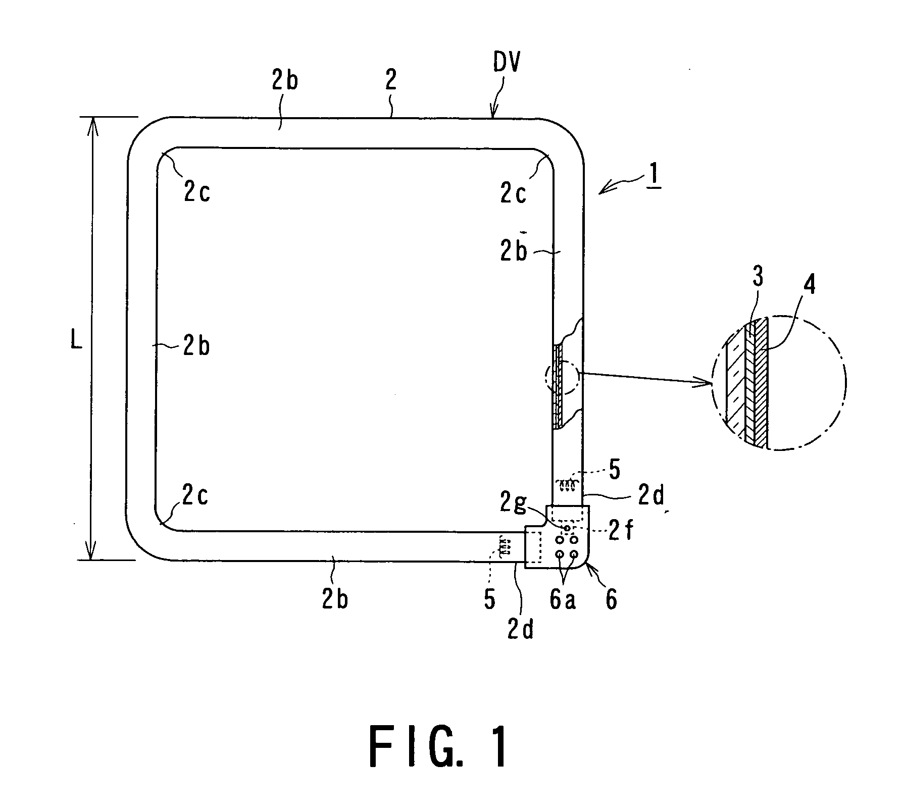
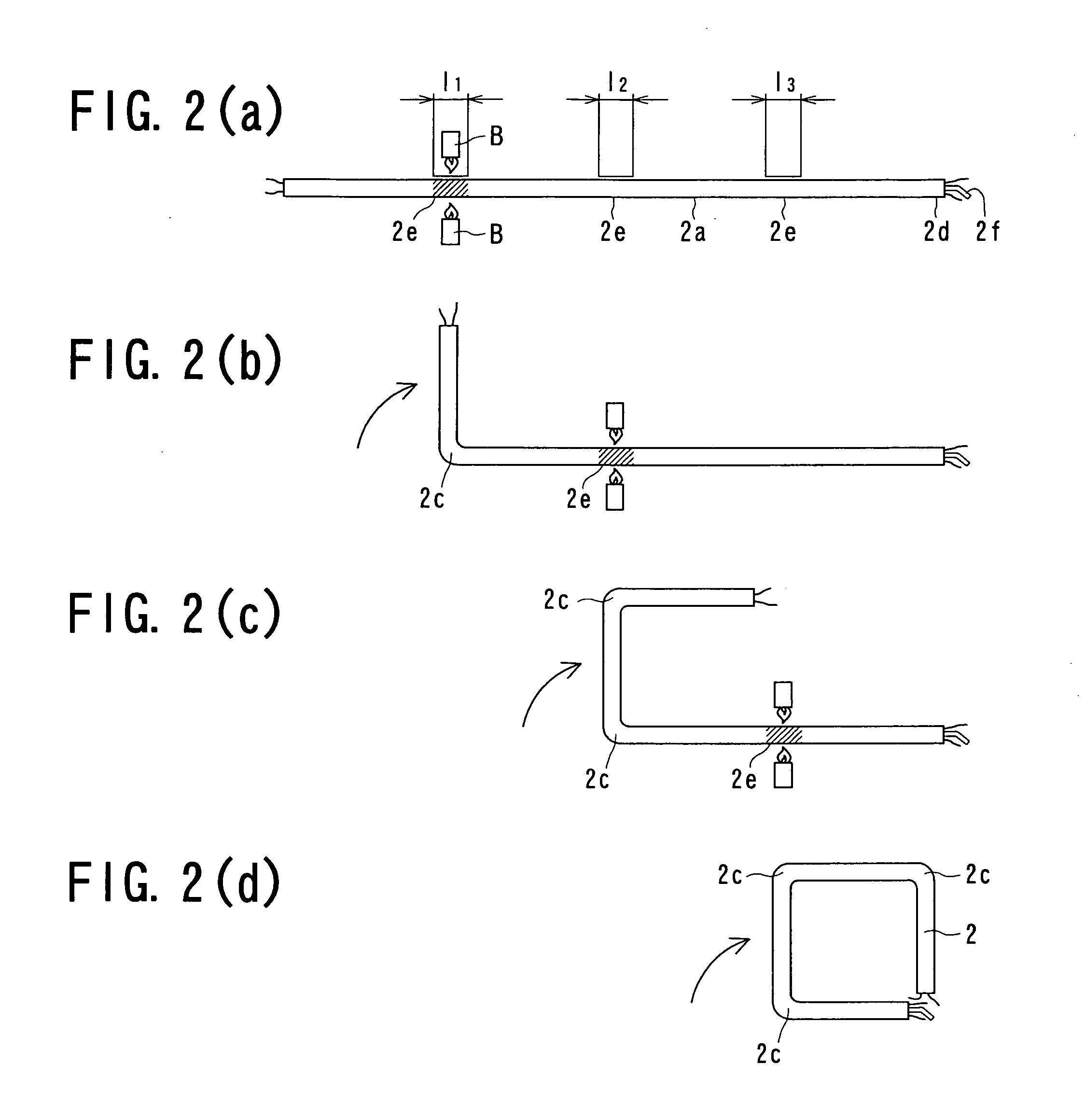
[0126]FIG. 1 and FIG. 2 illustrate the present invention, FIG. 1 being a front view of the fluorescent lamp and FIG. 2 includes illustrations for explaining the manufacturing process of the fluorescent lamp shown in FIG. 1.

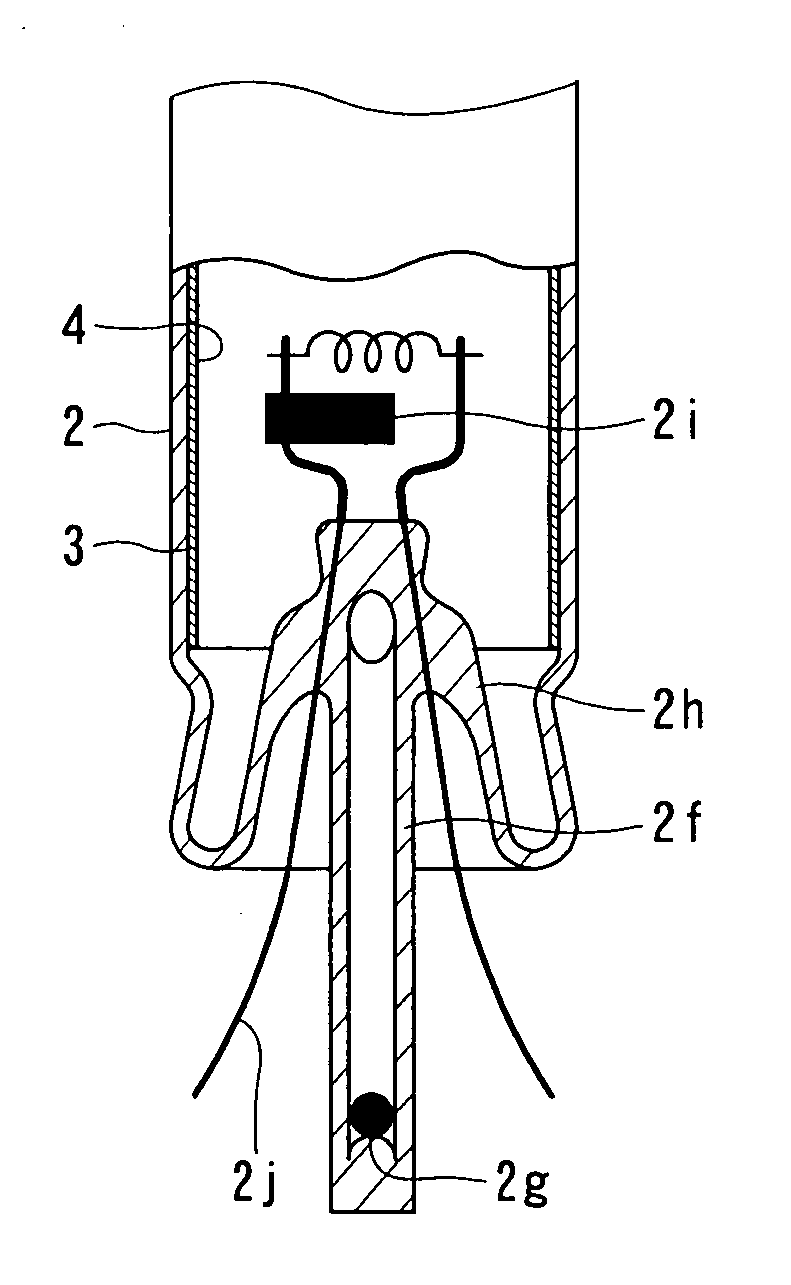
[0127] In the drawings, reference numeral 1 denotes a fluorescent lamp having a discharge vessel DV and a base 6. The discharge vessel DV is composed of a rectangular glass bulb 2 provided with the straight portions forming a substantially quadrate shape and having the following structure. That is, a discharge medium including a noble gas and mercury is sealed in the glass bulb. The noble gas is argon (Ar) gas, sealed at a pressure of approximately 320 Pa. The other known discharge agents such as neon, krypton, xenon, etc., may be used as the noble gas in addition to or instead of the argon.

[0128] A protective layer 3 formed of fine particles of metal oxide is formed on the inner face of the glass bulb 2, and a phosphor layer 4 made up of fine particles of a thre...

second embodiment

[0153] Hereunder, the present invention will be described. In this second embodiment, the metal oxide constituting the protective layer 3 has fine particles of γ (gamma) alumina with an average grain diameter of approximately 5.0 to 50 nm, the surface area is 80 m2 / g or more, and the amount of fine particles applied per surface area in the bulb is 0.01 to 0.1 mg / cm2.

[0154] In the case of the second embodiment, even if the amount of protective layer 3 applied is reduced and the film thickness thereof is also reduced, the straight tube portions 2b are essentially not stretched, and thermal deterioration of the phosphor layer 4 of the straight tube portions 2b in the bent portion forming step is small. Moreover, since the thickness of the protective layer 3 is small, the functions of the protective layer 3 can be sufficiently exhibited while suppressing the causing of the cracking at the bent portions 2c. Furthermore, the specific surface of the fine particles is 80 m2 / g or more, so th...

fourth embodiment

[0156]FIG. 4 is a front view illustrating a fluorescent lamp 1B of the present invention. The present embodiment has a base 6B provided so as to bridge the end portions 2d and 2d of the glass bulb 2 and the straight tube portion 2b on the opposing side. The base pins 6a serving as power-supplying portions is provided at the center position of the rectangular shape of the bulb 2. Furthermore, a lamp holding mechanism to be mounted to a lamp holder of a lighting apparatus, not shown, side is provided near the power supplying member such that electrical connection is established at the same time of mounting the lamp to the lighting apparatus. By forming the base 6B in this way so as to bridge the two opposing sides of the square shape, the bulb 2 can be more stably supported and the attaching strength can be improved as well as improvement in the strength of the bulb 2 itself. In addition, by arranging the power supplying member to the approximate center of the square shape, the bulb 2...


PUM


Abstract

A fluorescent lamp 1 comprises: a bulb 2 formed by heating bent-portion-formation preordination portions of a single straight-tube-shaped bulb 2a having an external tube diameter of 12 to 20 mm and a tube length of 800 to 2500 mm, forming a plurality of bent portions 2c and straight tube portions 2b adjacent to the bent portions 2c by bending processing, such that the straight portions 2b are disposed generally within the same plane by way of the bent portions 2c, forming in close proximity a pair of end portions 2d and 2d with electrodes 5 and 5 sealed in so as to form a single discharge path through the straight tube portions 2b and bent portions 2c, forming a phosphor layer 4 on the inner face of the bulb, and sealing a discharge medium including mercury; and a base 6 provided on the end portions 2d and 2d of the bulb 2; whereby thermal deterioration of the phosphor layer 4 formed at the straight tube portions 2b is reduced so deterioration of the initial light flux is suppressed, allowing lighting at higher efficiency. According to the above configuration, a fluorescent lamp which is compact and capable of light with high efficiency, and with improved light output properties, and a light fixture using this fluorescent lamp, can be provided.

Description

TECHNICAL FIELD [0001] The present invention relates to a fluorescent lamp and a manufacturing method thereof, and to a lighting apparatus using the fluorescent lamp. BACKGROUND ART [0002] Fluorescent lamps of straight tube shapes, ring shapes, and single-ended shapes are known as general fluorescent lamps, and particularly, in view of recent demands for energy conservation and conservation of resources, a small-diameter ring-shaped fluorescent lamp for high-frequency lighting has been developed and produced as a product. This small-diameter ring-shaped fluorescent lamp is identified by the name “FHC” in products (see Patent Document 1). This small-diameter ring-shaped fluorescent lamp has approximately the same external diameter for the ring size as that of conventional ring-shaped fluorescent lamps, but the external diameter of the tube is made to be smaller, while ensuring brightness equal to or greater than that of the conventional ring-shaped fluorescent lamps, thereby satisfyi...

Claims


Application Information

Patent Timeline
IPC IPC(8): H01J1/62H01J63/04H01J9/24H01J61/30H01J61/32H01J61/35H01J61/42H01J61/72
CPCH01J9/247H01J61/30H01J61/307H01J61/322H01J61/72H01J2893/0027
Inventor NISHIMURA, KIYOSHIWATANABE, MIHOSHIBAHARA, YUSUKEOOTANI, KIYOSHIYAMADA, ICHIROYORIFUJI, TAKASHITODA, NAOYUKIOONO, HAJIMEEGAWA, KAZUOYOSHIDA, MASAHIKO
Owner TOSHIBA LIGHTING & TECH CORP
Why Eureka
Try Eureka