
Borehole conductivity simulator verification and transverse coil balancing

a conductivity simulator and borehole technology, applied in the field of apparatus design, can solve the problems of not providing a measure of vertical conductivity or anisotropy, cannot be detected individually, and difficult to detect hydrocarbon-bearing zones, so as to reduce the magnitude of additional signals, and reduce the magnitude of signals

Inactive Publication Date: 2006-07-27
BAKER HUGHES INC
View PDF39 Cites 22 Cited by
  • Summary
  • Abstract
  • Description
  • Claims
  • Application Information

AI Technical Summary

Benefits of technology

The patent describes a method and apparatus for preparing and evaluating a multicomponent induction logging tool with multiple transmitter and receiver coils. The tool is placed in a calibration area that is unaffected by external conductive parts. The method involves activating the first transmitter coil and measuring the signal in the first receiver coil, then moving the first coil to reduce the signal, and repeating the process with the second transmitter coil. The apparatus includes a borehole conductivity simulator and a processor to activate the first transmitter coil and measure the signal, while a device moves the first coil to reduce the signal. The technical effects of this invention include improved accuracy and reliability of multicomponent induction logging tools, as well as simplified and efficient preparation and evaluation methods.

Problems solved by technology

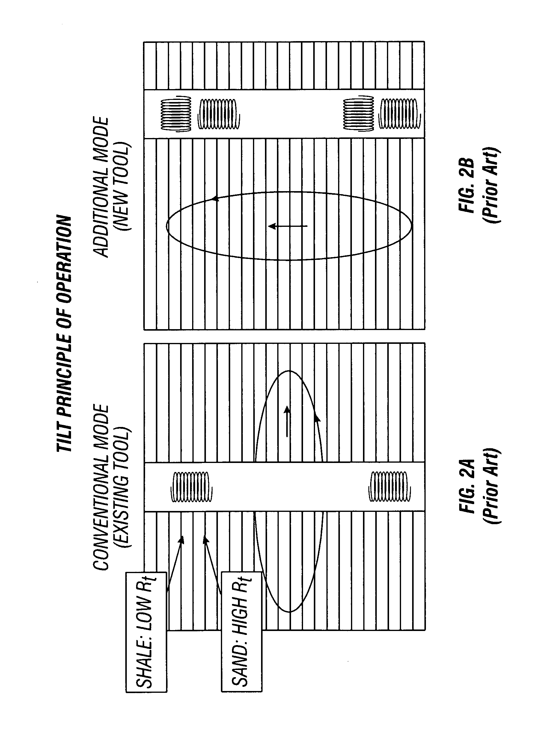
In general, when using a conventional induction logging tool with transmitters and receivers (induction coils) oriented only along the borehole axis, the hydrocarbon-bearing zones are difficult to detect when they occur in multi-layered or laminated reservoirs.
These reservoirs usually consist of thin alternating layers of shale and sand and, oftentimes, the layers are so thin that due to the insufficient resolution of the conventional logging tool they cannot be detected individually.
Conventional induction logging devices, which tend to be sensitive only to the horizontal conductivity of the formations, do not provide a measure of vertical conductivity or of anisotropy.
One, if not the main, difficulties in interpreting the data acquired by a transversal induction logging tool is associated with vulnerability of its response to borehole conditions.
There are a few hardware margins and software limitations that impact a conventional transversal induction logging tool performance and result in errors appearing in the acquired data.
The general hardware problem is typically associated with an unavoidable electrical field that is irradiated by the tool induction transmitter simultaneously with the desirable magnetic field, and it happens in agreement with Maxwell's equations for the time varying field.
The transmitter electrical field interacts with remaining modules of the induction logging tool and with the formation; however, this interaction does not produce any useful information.
Indeed, due to the always-existing possibility for this field to be coupled directly into the receiver part of the sensor section through parasitic displacement currents, it introduces the noise.
When this coupling occurs, the electrical field develops undesirable electrical potentials at the input of the receiver signal conditioning, primarily across the induction coil receiver, and this voltage becomes an additive noise component to the signal of interest introducing a systematic error to the measurements.
The problem could become even more severe if the induction logging tool operates in wells containing water-based fluids.
This circumstance apparently would result in a fact that capacitive coupling and associated systematic errors are environment dependant because capacitive impedance will be converse to the well mud permittivity.
However, geometry and layout effectiveness of Faraday shields becomes marginal and contradictory in the high frequency applications where conventional transverse induction tools can operate.
These limitations occur due to the attenuation these shields introduce to the magnetic field known in the art as a shield “skin effect”.
The shield design limitations are unavoidable and, therefore, the possibility for the coupling through displacement currents remains.
Another source of hardware errors introduced into the acquired log data is associated electrical potential difference between different tool conductive parts and, in particular, between transmitter and receiver pressure housings if these modules are spaced apart or galvanically separated.
It can be noticed that employing the induction tool in the logging string where it has mechanical and electrical connections (including telemetry) with instruments positioned both above and below could also result in the appearance of the above-mentioned currents.
There is an additional problem that the potential difference creates in conventional tool layouts having transmitter and receiver electronic modules spaced apart and using interconnection wires running throughout the sensor (mandrel) section.
The time varying currents also generate a respective magnetic field that crosses induction receiver coils and induces error voltages.
Unfortunately, these error voltages are also environmentally dependent and their changes cannot be sufficiently calibrated out during tool manufacturing.
Another source of systematic errors introduced in the log data is directly determined by uncertainties in mechanical dimensions of multi-component transmitter and receiver coils in the sensor section related both to their overall dimensions and positions with respect to each other.
However, even slight physical assembly deviations in the coil wires position and non-uniform coil form material temperature dependencies might destroy a factory pre-set bucking (compensation of the transmitter primary magnetic field coupled in the receiver coil) during well logging, and create non-recoverable errors due to mechanical displacement or imperfections.

Method used


Image

  • Borehole conductivity simulator verification and transverse coil balancing
  • Borehole conductivity simulator verification and transverse coil balancing
  • Borehole conductivity simulator verification and transverse coil balancing

Examples


Embodiment Construction

[0037] The instrument structure provided by the present invention enables increased stability and accuracy in an induction wellbore logging tool and its operational capabilities, which, in turn, results in better quality and utility of wellbore data acquired during logging. The features of the present invention are applicable to improve the structure of a majority of known induction tools.

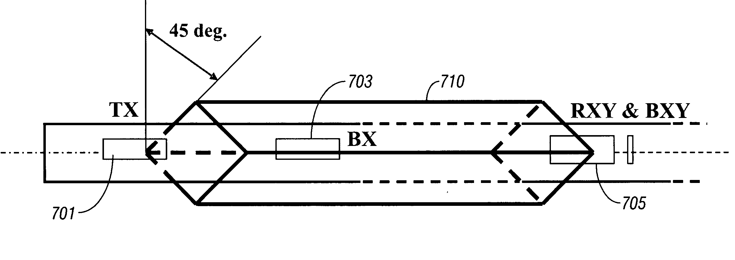
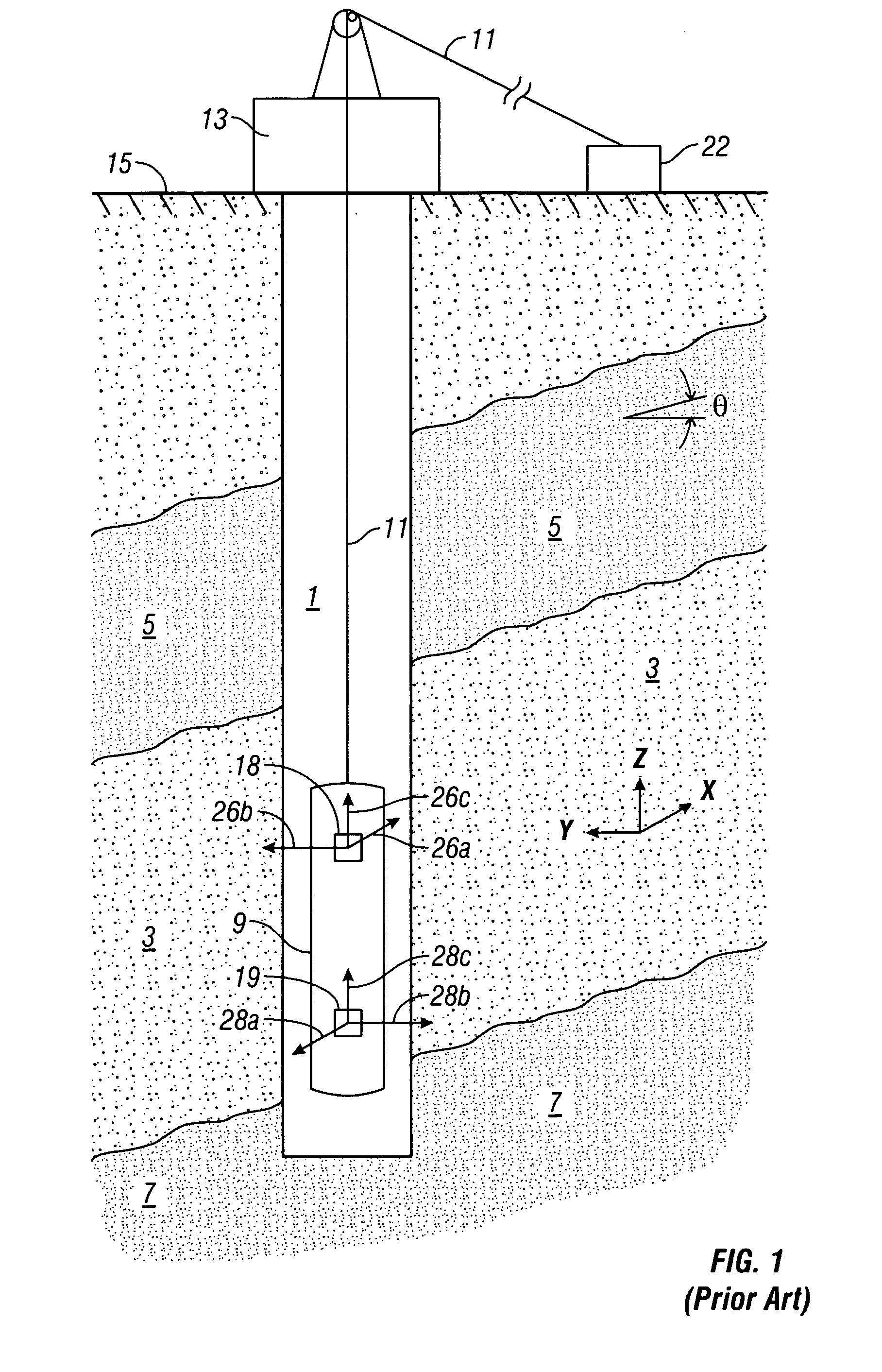
[0038] The invention will now be described in more detail and by way of example with reference to the accompanying drawings. FIG. 1 schematically shows a wellbore 1 extending into a laminated earth formation, into which wellbore an induction logging tool as used according to the present invention has been lowered. The wellbore in FIG. 1 extends into an earth formation which includes a hydrocarbon-bearing sand layer 3 located between an upper shale layer 5 and a higher conductivity than the hydrocarbon bearing sand layer 3. An induction logging tool 9 used in the practice of the invention has been ...


PUM


Abstract

Calibration of the arrays of a multicomponent induction logging tool is achieved by positioning the tool horizontally above ground. The upper and lower housings of the tool are connected by a borehole conductivity simulator which as a resistance comparable to that of a borehole. Axial and radial positioning of the transmitter coils is done by monitoring outputs at receiver coils to achieve a minimum.

Description

CROSS REFERENCE TO RELATED APPLICATIONS [0001] The present invention is a continuation-in-part of patent application Ser. No. 10 / 841,397 filed on May 7, 2004.BACKGROUND OF THE INVENTION [0002] 1. Field of the Invention [0003] The present invention is related to the field of apparatus design in the field of oil exploration. In particular, the present invention describes a method for calibrating multicomponent logging devices used for detecting the presence of oil in boreholes penetrating a geological formation. [0004] 2. Description of the Related Art [0005] Electromagnetic induction resistivity well logging instruments are well known in the art. Electromagnetic induction resistivity well logging instruments are used to determine the electrical conductivity, and its converse, resistivity, of earth formations penetrated by a borehole. Formation conductivity has been determined based on results of measuring the magnetic field of eddy currents that the instrument induces in the formatio...

Claims


Application Information

Patent Timeline
Patent Type & Authority Applications(United States)
IPC IPC(8): G01V3/18
CPCG01V3/28
Inventor FORGANG, STANISLAV W.GOLD, RANDYPELEGRI, LUIS M.CROSSKNO, MICHAEL S.
Owner BAKER HUGHES INC
Learn More