Method for fabrication of low-polarization implantable stimulation electrode

a low-polarization, electrode-based technology, applied in the direction of manufacturing tools, superimposed coating processes, therapy, etc., can solve problems such as interference with cardiac signal sensing, and achieve the effect of preventing oxidation of the adhesion layer surface and preventing delamination of the ruox coating

Inactive Publication Date: 2006-07-27
MEDTRONIC INC
View PDF27 Cites 52 Cited by
  • Summary
  • Abstract
  • Description
  • Claims
  • Application Information

AI Technical Summary

Benefits of technology

[0005] In another embodiment, a method for fabricating a low post-pulse polarization electrode includes applying an adhesion layer to the electrode surface prior to depositing the RuOx coating to prevent delamination of the RuOx coating. The adhesion layer is formed of titanium (Ti) or zirconium (Zr) and applied in a vacuum environment to prevent oxidation of the adhesion layer surface.

Problems solved by technology

Following delivery of a cardiac pacing pulse by an electrode, an after-potential typically remains on the electrode which persists for a sufficient period of time thereafter, that can interfere with sensing of cardiac signals associated with tissue depolarization caused by the delivered pulse.

Method used


Image

  • Method for fabrication of low-polarization implantable stimulation electrode
  • Method for fabrication of low-polarization implantable stimulation electrode
  • Method for fabrication of low-polarization implantable stimulation electrode

Examples


Embodiment Construction

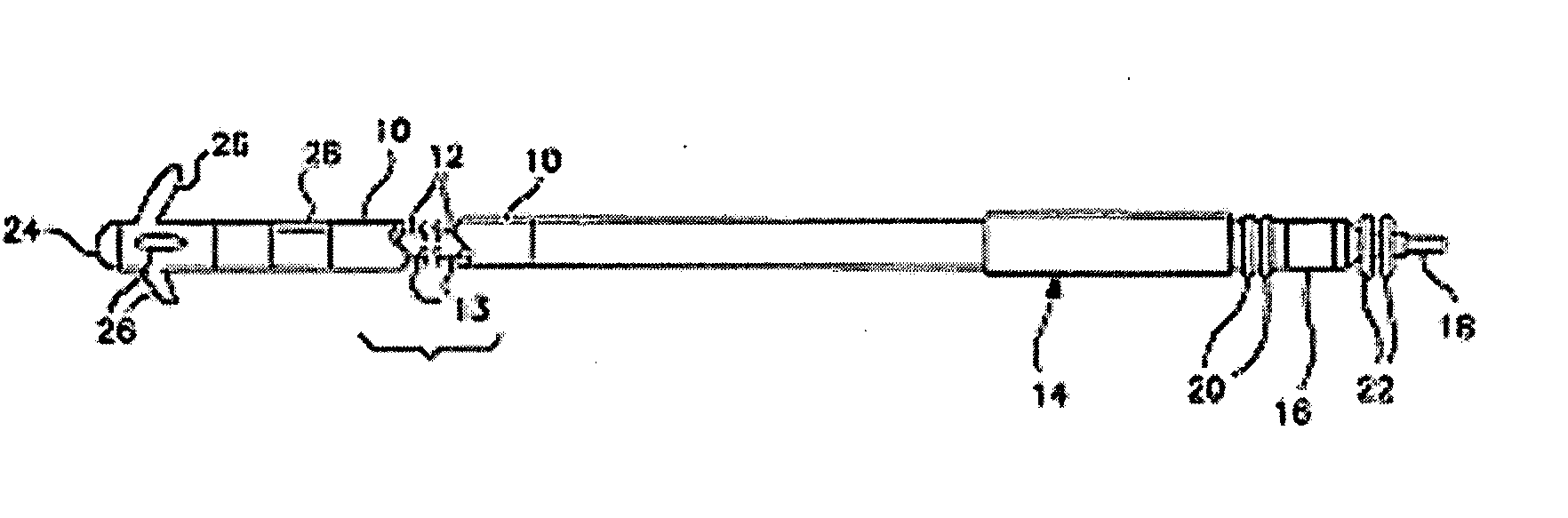
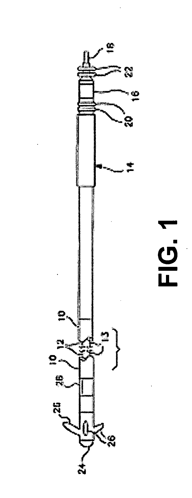
[0011]FIG. 1 is a plan view of one type of cardiac pacing lead in which the invention may usefully be practiced. In the case of FIG. 1, the lead is an endocardial pacing lead provided with an elongated insulative outer sheath 10 which carries two mutually insulated conductors 12 and 13; illustrated schematically. At the proximal end of the lead is an in-line bipolar connector assembly 14 which may correspond to the IS-1 connector standard. Connector assembly 14 is provided with a connector ring 16 coupled to conductor 12 and a connector pin 18 coupled to conductor 13. Sealing rings 20 and 22 are provided to seal the connector assembly within the bore of an associated cardiac pacemaker and to prevent fluid leakage between connector ring 16 and connector pin 18.

[0012] The proximal end of the lead carries a pacing cathode 24 and a pacing anode 28. Pacing cathode 24 may be any known type of pacing cathode employed in the context of cardiac pacing leads, however, it is illustrated as ta...


PUM

PropertyMeasurementUnit
poweraaaaaaaaaa
thicknessesaaaaaaaaaa
thicknessaaaaaaaaaa

Abstract

A method for fabricating an implantable medical electrode includes roughening the electrode substrate, applying an adhesion layer, and depositing a valve metal oxide coating over the adhesion layer under conditions optimized to minimize electrode impedance and post-pulse polarization. The electrode substrate may be a variety of electrode metals or alloys including titanium, platinum, platinum-iridium, or niobium. The adhesion layer may be formed of titanium or zirconium. The valve metal oxide coating is a ruthenium oxide coating sputtered onto the adhesion layer under controlled target power, sputtering pressure, and sputter gas ratio setting optimized to minimize electrode impedance and post-pulse polarization.

Description

FIELD OF THE INVENTION [0001] The present invention relates to implantable stimulation electrodes generally and more particularly to implantable stimulation electrodes fabricated to reduce post pulse polarization. BACKGROUND OF THE INVENTION [0002] Following delivery of a cardiac pacing pulse by an electrode, an after-potential typically remains on the electrode which persists for a sufficient period of time thereafter, that can interfere with sensing of cardiac signals associated with tissue depolarization caused by the delivered pulse. This phenomenon has been addressed in a number of ways over the years, and quite a large variety of electrode coatings have been developed in an effort to reduce post pulse polarization effects. One of the most common approaches to reducing post pulse polarization is to provide a high surface area coating having micron or sub-micron size surface features, such as a porous sintered metallic coating as described in U.S. Pat. No. 4,280,514 issued to Ma...

Claims


Application Information

Patent Timeline
Patent Type & Authority Applications(United States)
IPC IPC(8): A61N1/05
CPCY10T29/49204A61N1/05B24C1/06B24C3/322C23C28/32
Inventor NYGREN, LEA A.COLES, JAMES A. JR.BRABEC, SCOTT J.ROSE, RANDY G.
Owner MEDTRONIC INC
Why Eureka
Try Eureka