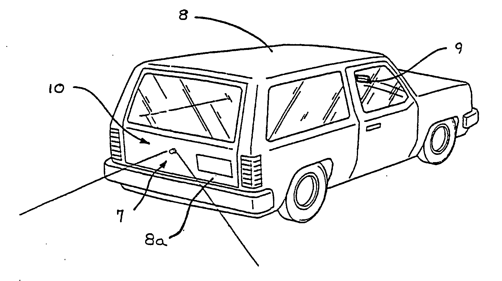
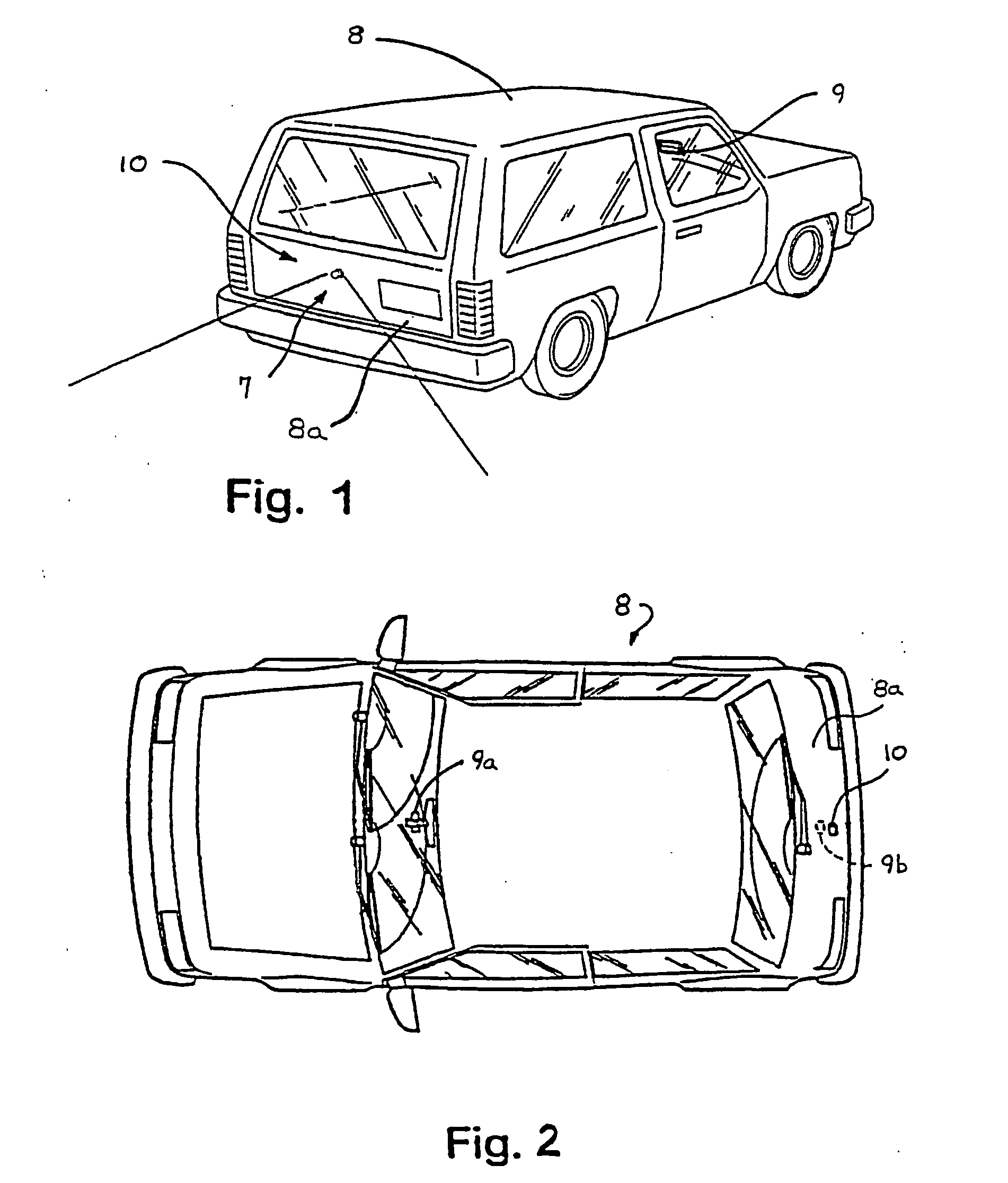
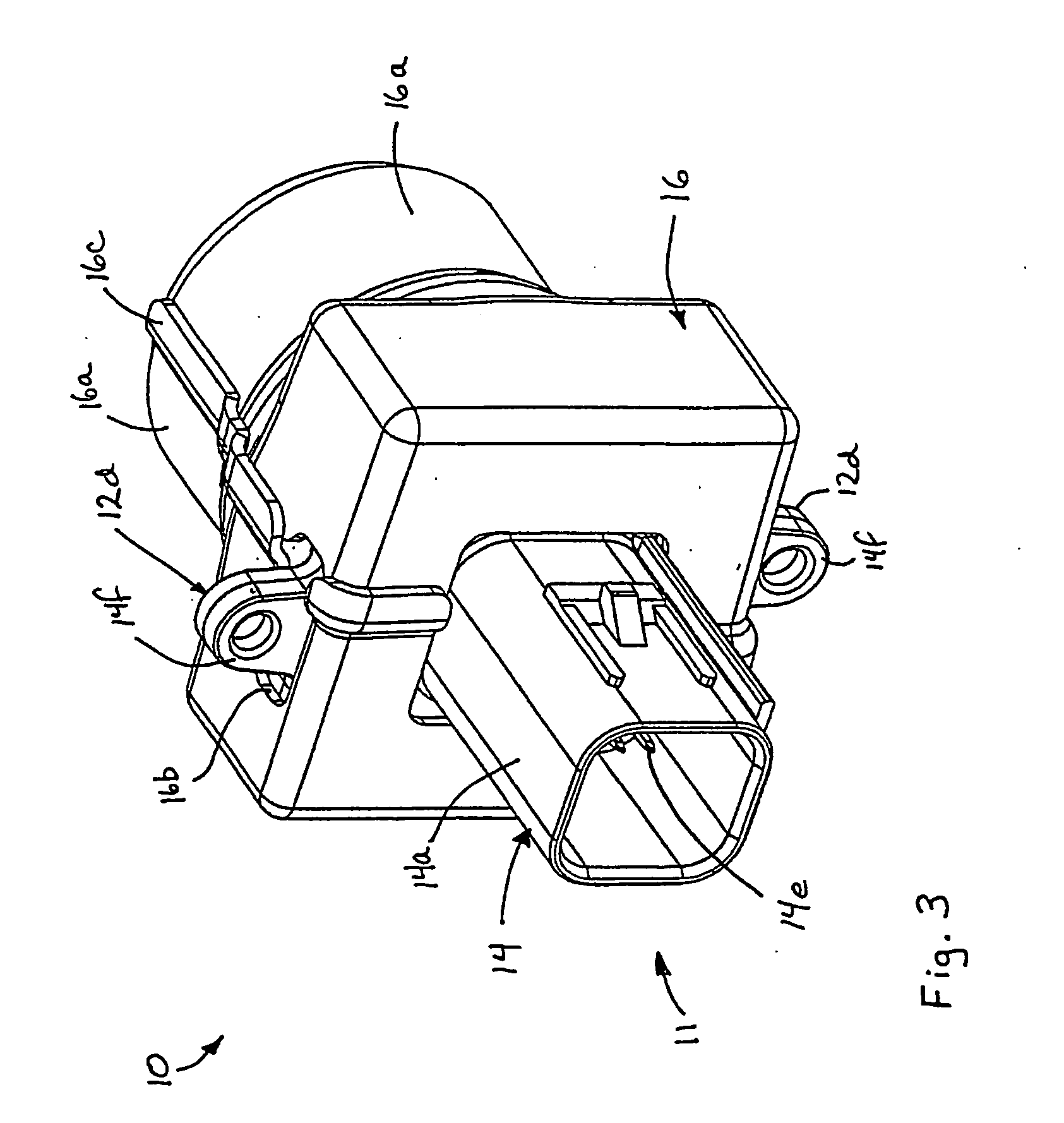
[0009] The present invention is intended to provide a
camera module which includes a camera or image sensor and a circuit board positioned within a housing, which may be
laser welded or sonic welded or the like to substantially seal the camera and circuit board within the housing. The housing, preferably molded of a plastic material, may include a plastic molded connector extending therefrom, such that the camera housing and connector are configured as a single unitary module. The camera module may include a
heating element for heating a transparent cover at the lens (or for heating the lens itself) of the camera to assist in defogging or
defrosting the transparent cover in
cold weather conditions. The transparent cover may have a transparent
conductive coating (such as an
indium tin oxide (ITO)
coating or doped
tin oxide or a
metal grid or the like), preferably on its inner surface, such that contact of a power terminal (connected to or in communication with or powered by a battery or other power source of the vehicle) and a ground terminal of the heating elements at the
conductive coating causes heating of the
coating to defrost or defog the cover. The heating elements or terminals may be actuated in response to a control or
thermostat, which functions to activate and deactivate the
heating element at predetermined temperatures sensed by a temperature sensor at or in the camera module or elsewhere at, in or on the vehicle. The present invention thus provides a camera module that maintains the camera or imaging sensor and is substantially impervious to environmental elements, such as rain,
snow,
dirt, dust, road splash,
road debris and the like. The present invention also provides at least partial, and preferably substantial, reduced vibration affects of the camera or image sensor.
[0016] According to yet another aspect of the present invention, a camera module for a vehicle comprises a housing, a transparent cover at a portion of the housing, an image sensor, at least one
heating element and a control. The image sensor is positioned within the housing and is operable to receive an image of a scene exteriorly of the housing through the transparent cover. The heating element is operable to heat the transparent cover. The control is operable to activate the heating element in response to a temperature sensor. The heating element is activatable to heat the transparent cover to reduce
fog and / or ice on the transparent cover.
[0026] For example, the imaging system may selectively activate visible or
infrared or near
infrared illumination sources or light emitting diodes (LEDs) in response to a detected ambient
light level dropping or decreasing or lowering to a threshold level. The imaging system may also or otherwise selectively switch the imaging sensor from a color mode to a black and white mode in response to the reduced ambient
light level. Optionally, the imaging system may apply an
infrared contribution correction to the detected levels for each color (such as red, green, blue) detected by the imaging sensor to adjust the
color balance of the imaging sensor for better color rendition in the captured images. Optionally, the imaging system may provide visible illumination to the exterior scene and may limit or block infrared and
near infrared light present in the illuminated scene to reduce
processing requirements to obtain the appropriate
color balance in the captured images.
[0027] Therefore, the present invention provides a camera module for a vehicle which may be substantially hermetically sealed to limit or substantially preclude water intrusion or the like into the housing of the module, or which may be vented to allow for
water vapor to enter or exit the module. The camera housing may also include a heating element which is operable to defrost or defog the transparent cover of the module and / or to heat the compartment of the camera housing to limit or substantially preclude condensation from forming within the module. The heating element may be activated and deactivated at predetermined temperatures in response to a temperature sensor and / or
thermostat. The transparent cover of the housing may include a
conductive coating on a surface thereof, such that applying an
electrical current or flow through or across the coating on the surface of the transparent cover functions to heat the surface of the cover to defrost or defog the transparent cover. The present invention thus provides an environmentally resilient, protected, economical camera module which may be mounted to a vehicle and connected or plugged into a wiring connector of the vehicle.
[0028] The present invention thus also provides a camera housing device that is movable or adjustable to move a camera or imaging sensor between an operational position and a stored position. The camera thus may be positioned in a stored position within an exterior portion of the vehicle when not in use. The exterior panel of the camera housing device may provide an exterior cover at the exterior portion of the vehicle to protect the camera and lens from the elements when they are not in use. The housing device may include a transparent panel that substantially encloses the camera and lens within the housing. The housing device may also include a panel cleaning device that may clean the transparent panel to limit or substantially preclude
dirt buildup or debris on the panel that may adversely effect the performance of the camera and thus of the imaging system.
[0029] The present invention also provides an imaging system that is capable of providing a
color image during
daytime conditions, and that may provide a black and white image, with or without additional infrared or near infrared illumination provided to the scene, during darkened or nighttime conditions. The imaging system may correct the
color image to account for infrared and near infrared illumination that may be present in the exterior scene, in order to provide an image with proper or desired
color balance. The present invention thus may provide optimal images to the driver of the vehicle during substantially all types of lighting conditions.


