Customized corneal flap

a corneal flap, custom technology, applied in the field of corrective optical surgery, can solve the problems of not all eyes, however, being able to characterize vision difficulties in the human eye, and affecting the quality of vision of patients

Inactive Publication Date: 2006-08-03
TECHNOLAS PERFECT VISION
View PDF15 Cites 27 Cited by
  • Summary
  • Abstract
  • Description
  • Claims
  • Application Information

AI Technical Summary

Benefits of technology

[0017] Once the topology of the cornea has been defined and the prototypic dissection path has been identified, the two are then used together to predict whether HOAs will be induced or affected by cutting corneal tissue along the prototypic dissection path. Beyond this, the topology of the cornea can also be used to identify any pre-existing HOAs that may be present. After these predictions and identifications have been made, the prototypic dissection path can be refined to compensate for the predicted effects of the topology. For the present invention, this refinement is essentially a two-step process. In the first step, the prototypic dissection path is refined in order to eliminate or minimize the inducement of HOAs that may result during the laser surgical procedure. In the second step, the refined prototypic dissection path may then be even further refined to correct for pre-existing HOAs. In this manner, the present invention compensates for both topological and anatomical effects on HOAs.
[0019] For the present invention, HOAs that may be induced when corneal tissue is cut during a laser surgical procedure are minimized or eliminated by appropriately altering the course of the prototypic dissection path. In particular, by altering the course of the prototypic dissection path, the refined prototypic dissection path can be established to accommodate the redistribution of biomechanical stresses in the cornea that would otherwise result when the corneal tissue is cut. Without more, however, course alteration alone will not correct for the pre-existing HOAs.

Problems solved by technology

Not all eyes, however, are perfect.
The consequences of this are that light path lengths through the eye become distorted and are not all equal to each other.
In general, vision difficulties in the human eye can be characterized by the changes and differences in optical path lengths that occur as light transits through the eye.
Indeed, nearly one half of the world's population suffers from imperfect visual perception.
For example, many people are nearsighted because the distance between the lens and retina is too long (myopia).
This happens because the distance between the lens and retina is too short.
Further, in addition to the more simple refractive errors mentioned above, the human eye can also suffer from higher order refractive errors (“aberrations”) such as coma, trefoil and spherical aberration.
Spherical aberration results from loss of definition of images that are formed by optical systems, such as an eye.
In some cases, these distortions occur in a very complex way.
In the trivial case, non-higher order distortions like nearsightedness and farsightedness would result in an uncomplicated bowl-like symmetrical distortion.
With HOAs, however, the result is a complex non-symmetrical distortion of the originally flat wavefront.
It is these non-symmetrical distortions which are unique for every optical system (e.g., a person's eye), and which lead to blurred optical imaging of viewed scenes.
While a typical approach for improving the vision of a patient has been to perform refractive surgery on the eye to eliminate distortions, the surgery itself can lead to an increase in HOAs, both immediately and during recovery.
While inducing fewer HOAs, the use of femtosecond lasers to create a flap in the cornea has not led to the complete elimination of such changes.
Regardless of their source, however, HOAs can be troublesome and, if possible, should be corrected.

Method used


Image

  • Customized corneal flap
  • Customized corneal flap
  • Customized corneal flap

Examples


Embodiment Construction

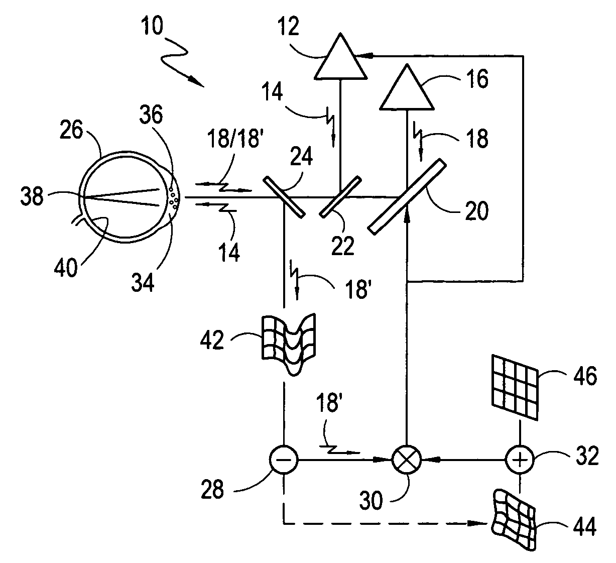
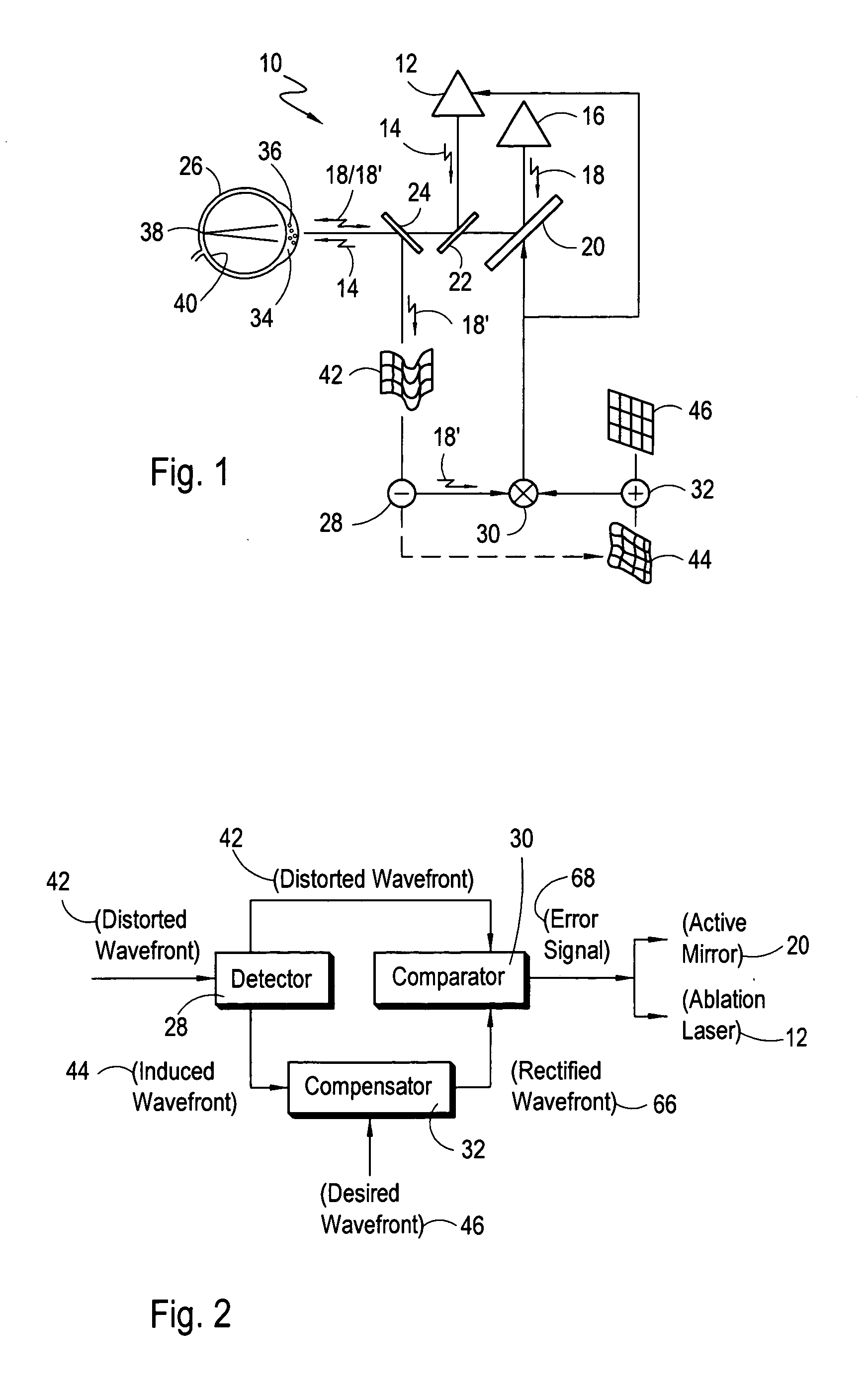
[0031] Referring initially to FIG. 1, a system for creating a customized corneal flap in accordance with the present invention is shown and is generally designated 10. In detail, the components of system 10 include a source 12, such as a femtosecond laser, for generating an ablation laser beam 14, and a source 16 for generating a diagnostic laser beam 18. Further, the system 10 includes an active, multi-facet mirror 20, a beam splitter 22 and a beam splitter 24. More particularly, the active mirror 20 is preferably of a type disclosed in U.S. Pat. No. 6,220,707 which issued to Bille for an invention entitled “Method for Programming an Active Mirror to Mimic a Wavefront” and which is assigned to the same assignee as the present invention. As shown, the active mirror 20 and the beam splitters 22 and 24 direct the diagnostic laser beam 18 from the diagnostic laser source 16 toward an eye 26. Likewise, the beam splitters 22 and 24 are used to direct the ablation laser beam 14 from the a...


PUM

PropertyMeasurementUnit
transparentaaaaaaaaaa
dimensionsaaaaaaaaaa
diameteraaaaaaaaaa

Abstract

A method and system for customizing a flap created from a transparent material compensates for aberrations, particularly higher order aberrations, which are pre-existing or otherwise induced during creation of the flap. Before flap creation, the distorted wavefront of the transparent material is determined and the topology of the transparent material is defined in order to predict contributions likely to be encountered or induced by the stress distribution during creation of the flap. In view of the topology of the transparent material, a prototypic dissection path based on the distorted wavefront is refined to establish a refined dissection path. As a result, the flap is created along the refined dissection path to correct and minimize or eliminate the formation of higher order aberrations.

Description

[0001] This application is a continuation-in-part of pending application Ser. No. 11 / 033,967 filed Jan. 12, 2005, which is, in turn, a continuation-in-part of U.S. Pat. No. 6,887,232, which issued on May 3, 2005. The contents of application Ser. No. 11 / 033,967 and U.S. Pat. No. 6,887,232 are incorporated herein by reference.FIELD OF THE INVENTION [0002] The present invention pertains generally to methods and systems used in corrective optical surgery. More particularly, the present invention pertains to methods and systems that create a flap in the cornea during corrective optical surgery. The present invention is particularly, but not exclusively, useful as a method and system in which the anatomical conditions of a patient's eye are used to predict the effects of the creation of a corneal flap and to provide a surgical plan that compensates for such effects. BACKGROUND OF THE INVENTION [0003] In the perfect eye, an incoming beam of light is focused through the cornea and through t...

Claims


Application Information

Patent Timeline
Patent Type & Authority Applications(United States)
IPC IPC(8): A61B18/18A61F9/007A61B17/00A61F9/01
CPCA61B3/1015A61B3/107A61B2017/00017A61B2017/00022A61F9/008A61F9/00829A61F2009/00848A61F2009/00872A61F2009/0088
Inventor BILLE, JOSEF
Owner TECHNOLAS PERFECT VISION
Why Eureka
Try Eureka