
Ink jet-use receptive layer forming method and device, and disk formed with ink jet-use receptive layer

a technology of ink jet and receiving layer, which is applied in the field of ink jet use receptive layer forming method and device, and disk formed with ink jet use receptive layer, can solve the problems of unsatisfactory ink receiving capability of receiving layer formed from uv curable resin, prone to bleeding, and high cost of offset printing process for printing labels on this type of low-volume cd run, so as to improve the effect of preventing wrinkling or crack

Inactive Publication Date: 2006-08-10
MITSUBISHI PAPER MILLS LTD +1
View PDF0 Cites 17 Cited by
  • Summary
  • Abstract
  • Description
  • Claims
  • Application Information

AI Technical Summary

Benefits of technology

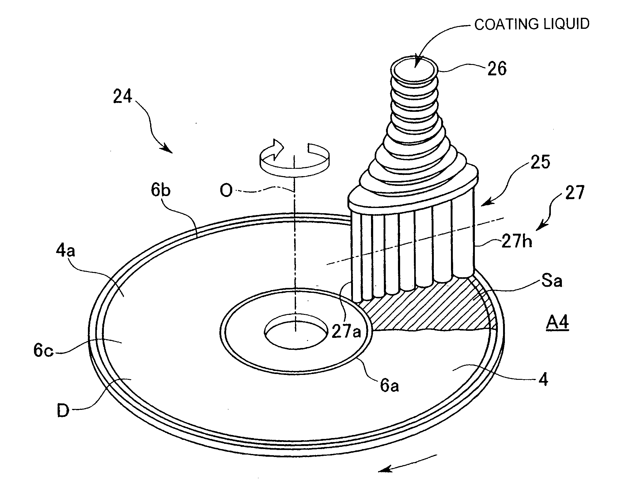
[0023] According to this above aspect of the present invention, the coating film applied within the application region that has been partitioned off by the partitions is formed flat, and with a uniform film thickness, right up to the boundaries formed by the partitions, and leakage of the coating liquid outside the application region can be prevented. Because the partitions ensure that the coating liquid adequately reaches the boundaries of the application region, the phenomenon wherein the drying of the boundary portions of the coating film proceeds more quickly than that of the central region can be suppressed, and the problem caused by the coating liquid from the boundary portions moving during drying and causing variation in the film thickness can be effectively prevented.
[0050] Drying of the coating film is preferably conducted using a heating device positioned underneath the disk, using a temperature gradient that falls gently from the inside edge towards the outside edge of the coating film. By using this type of drying operation, the phenomenon in which a film forms on the surface of the coating in the early stages of drying, and vapor from the inside of the coating film then bursts through this film, causing irregularities in the surface of the coating film, can be prevented, and because this process also allows better prevention of wrinkling or cracking of the coating film during drying, an inkjet receiving layer of superior flatness can be formed.

Problems solved by technology

The use of the type of offset printing processes described above for printing the labels on this type of low-volume CD run is extremely expensive, due to the costs associated with preparatory processes such as editing, plate preparation, and color matching and the like, which are necessary for the type of offset printing, and is consequently unsuitable.
Hei 9-245380, the ink receiving capability of the receiving layer formed from the UV curable resin is unsatisfactory, and the bleeding is prone to arise during printing with an inkjet printer or the like.
As a result, the resolution of the printed image on the receiving layer is poor, meaning that particularly in those cases where a photograph or the like is printed, a clear image cannot be obtained.
Hei 6-270530 can be applied to form a receiving layer using the various application devices listed above if the application target is in a raw fabric or sheet form, these application devices are unsuited to forming a uniform coating across an annular-shaped application area, such as that found on the surface of an optical disk.
In addition, because the solid content in the coating liquid is approximately 20% at the time of application, the viscosity is overly low, meaning it is very difficult to achieve a smooth application of the coating on a disk surface using the type of screen printing and spin coating methods that have conventionally been used for printing on optical disk or the like.
However, because this method uses a single nozzle for the application, the associated productivity is poor, and because the application takes a considerable length of time, the coating liquid is prone to a loss of flowability, which makes leveling difficult to achieve.
If an attempt is made to shorten the application time, then the rotational speed of the disk must be raised, but this causes the coating liquid to move due to the increased centrifugal force, causing a deterioration in the uniformity of the film thickness.
However, with a method such as this, where a set of aligned nozzles are simply moved in a straight line and used to apply equal quantities of an application liquid, the formation of a uniform coating on an annular-shaped application target is essentially impossible, even if the supply rate of the application liquid is controlled, and an efficient application cannot be achieved.
However, the method disclosed in this application is based on the premise of spin coating, and is unable to improve the shortcoming of conventional spin coating methods, namely, the fact that the limitation for applicable viscosity of the coating film exists, and that the thickness of the final coating film have gradient across the radius of the disk.
Moreover, in each of the application methods described above, even assuming a coating liquid of uniform thickness is able to be applied to the surface of the disk, the problem described below can still not be resolved.
In such cases, because the film thickness is reduced within the inner peripheral region 104b and the outer peripheral region 104c of the receiving layer 104, the ink receiving capability of these regions diminishes, meaning they are prone to be supplied with too much ink for the ink receiving capability during printing, which can cause the ink to bleed and make it difficult to achieve a clear printed image.

Method used


Image

  • Ink jet-use receptive layer forming method and device, and disk formed with ink jet-use receptive layer
  • Ink jet-use receptive layer forming method and device, and disk formed with ink jet-use receptive layer
  • Ink jet-use receptive layer forming method and device, and disk formed with ink jet-use receptive layer

Examples


modified examples

[0140] As follows is a description of modified examples of the process and apparatus 10 for forming a receiving layer according to the example described above. Those members or components that are either identical or similar to components within the example described above are described using the same reference symbols.

[0141] Modified examples of the concave grooves 6a and 6b are described with reference to FIG. 14 through FIG. 16.

[0142]FIG. 14 is a partial longitudinal cross-sectional view showing a concave groove 47 (47a and 47b) according to a first modified example. In the figure, the concave groove 47 is formed with a substantially square-shaped cross section, and this type of concave groove is formed around the entire inner peripheral boundary portion 5a and the entire outer peripheral boundary portion 5b of the annular-shaped receiving layer 5. The concave groove 47 is formed with a depth d across the entire width W, meaning that provided the depth d is set to a value that ...


PUM

PropertyMeasurementUnit
Fractionaaaaaaaaaa
Temperatureaaaaaaaaaa
Thicknessaaaaaaaaaa

Abstract

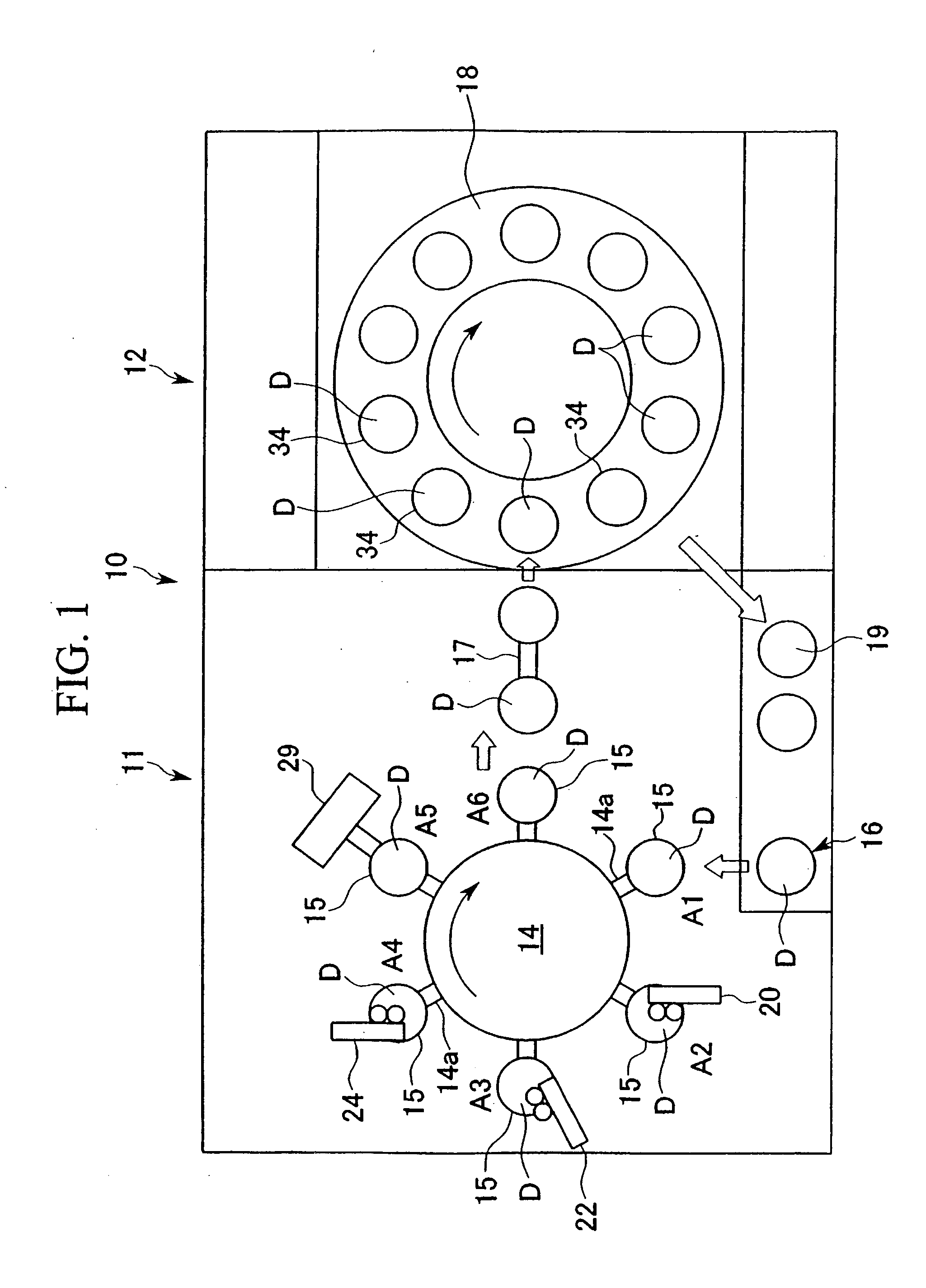
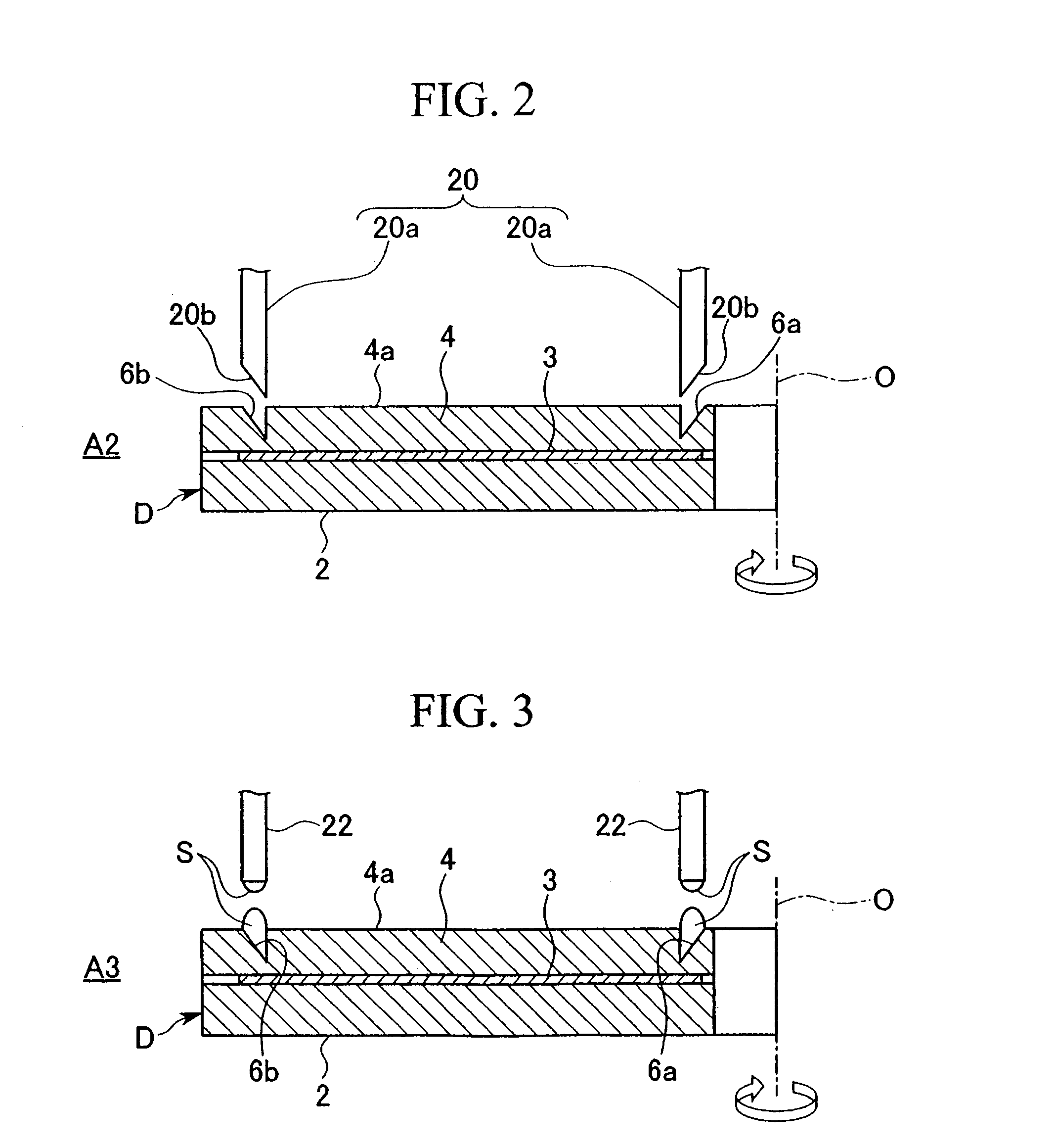
Concave grooves for forming a receiving layer for inkjet printing are provided at the inner peripheral and outer peripheral boundary portions of an application region on a disk substrate. The concave grooves are formed with a substantially V-shaped cross section, and with a depth d that is at least equal to the film thickness of the coating film within a central region between the concave grooves. A plurality of nozzles of a supply device is arrayed in a radial direction across the central region between the concave grooves, and a substantially constant quantity of coating liquid per unit of surface area is applied so as to form a coating film of a predetermined thickness. The applied coating liquid portions are flattened by a mutual leveling effect. During drying, the coating film inside the concave grooves does not dry first, but rather dries and contracts at substantially the same time as the coating film within the central region, meaning a receiving layer of uniform film thickness can be formed over the entire central region.

Description

TECHNICAL FIELD [0001] The present invention relates to a process and apparatus for forming a receiving layer for receiving ink supplied by an inkjet printer (hereafter referred to as an inkjet receiving layer), and also relates to a disk with an inkjet receiving layer formed thereon. More specifically, the present invention relates to a process and apparatus for forming a coating film that functions as an inkjet receiving layer on the surface of a flat disk, by applying a coating liquid, which contains water or an alcohol as the solvent, to the surface of the disk to form the coating film, and then drying the liquid, and also relates to a disk with this type of inkjet receiving layer formed thereon. [0002] Priority is claimed on Japanese Patent Application No. 2003-155599, filed May 30, 2003, the content of which is incorporated herein by reference. BACKGROUND ART [0003] Conventional optical disks include CDs and DVDs, and these optical disks have a structure wherein an information...

Claims


Application Information

Patent Timeline
IPC IPC(8): B05D3/06B05B7/06B41M5/00B05C5/02B41M5/50B41M5/52G11B7/24G11B7/24047G11B7/24094G11B7/24097G11B7/254G11B7/257G11B7/26G11B23/40
CPCB05C5/0208B05C5/027B41M5/0017B41M5/0088G11B7/266G11B23/40G11B7/26
Inventor EBISAWA, SHOUELMATSUMOTO, MASAAKITSUNEMATSU, NORIOFUJII, HIROYUKIYOKOTA, NOBUYUKI
Owner MITSUBISHI PAPER MILLS LTD
Learn More