System and method for adaptive bolus chasing computed tomography (CT) angiography

a computed tomography and adaptive technology, applied in the field of bolus chasing angiography, can solve the problems of over-estimation of stenosis, overlap of venous structures, and limited results of ct contrast bolus dynamics modeling, so as to achieve faster and more robust identification/estimation algorithms and techniques, and efficient implementation of bolus chasing imaging in practi

Inactive Publication Date: 2006-08-10
IOWA RES FOUND UNIV OF
View PDF15 Cites 69 Cited by
  • Summary
  • Abstract
  • Description
  • Claims
  • Application Information

AI Technical Summary

Benefits of technology

[0020] A method of utilizing bolus propagation and control for contrast enhancement comprises measuring with an imaging device a position of a bolus moving along a path in a biological structure. The method further comprises predicting a future position of the bolus using a simplified target model and comparing the predicted future position of the bolus with the measured position of the bolus. A control action is determined to eliminate a discrepancy, if any, between the predicted position of the bolus and the measured position of the bolus and the relative position of the imaging device and the biological structure is adaptively adjusted according to the control action to chase the motion of the bolus.
[0021] A system for utilizing bolus propagation and control for contrast enhancement comprises an imaging device for measuring a position of a bolus moving along a path in a biological structure. The system further comprises a predictor comprising a processor programmed for predicting a future position of the bolus using a simplified target model and a processor programmed for comparing the predicted future position of the bolus with the measured position of the bolus. A controller comprising a processor is programmed for determining a control action to eliminate a discrepancy, if any, between the predicted position of the bolus and the measured position of the bolus. The system further comprises an actuator for adaptively adjusting the relative position of the imaging device and the biological structure according to the control action to chase the motion of the bolus.

Problems solved by technology

However, the existing results on modeling of CT contrast bolus dynamics are very limited.
Scanning too early may result in over-estimation of stenosis, while scanning too late may result in overlap of venous structures.
For the test-bolus method, there is a risk of decreasing target lesion conspicuity due to equilibration of the test-bolus.
For the two triggering methods, they are vulnerable to patient motion, usually related to breathing, which may displace the target organ or vessel from the scan plane.
Moreover, one of the fundamental limitations with all the three methods is that they provide little data for matching the table / gantry translation to the contrast bolus propagation.
Bolus dynamics is complicated by multiple interacting factors involving the contrast administration protocol, imaging techniques, and patient characteristics.
In particular, the current patient table is translated at a pre-specified constant speed during data acquisition, which cannot be altered adaptively to chase the contrast bolus for optimally enhanced CT images.
With a pre-set scanning speed, it is difficult and often impossible to synchronize the central scanning plane with the longitudinal bolus position.
This misalignment becomes more problematic to image quality when spiral scanning speed is fast (with multi-slice spiral CT), contrast volume is small and / or injection rate is high (leading to reduced peak duration), as well as when there are large or small capacity vessels, either from aneurysm formation or occlusive disease.

Method used


Image

  • System and method for adaptive bolus chasing computed tomography (CT) angiography
  • System and method for adaptive bolus chasing computed tomography (CT) angiography
  • System and method for adaptive bolus chasing computed tomography (CT) angiography

Examples


example 1

[0105] Adaptive bolus chasing angiography was performed in a computer simulated clinical environment based on published values of blood velocities as shown in Table 1.

TABLE 1PeakMeanVelocityVelocityDiameter ± SD(cm / s)(cm / s)(cm)Aorta (Ao) 150 ± 30 27 ± 8.9 1.8 ± 0.2Common Iliac Artery (CIA) 125 ± NA13.5 ± 4.0  0.9 ± NAExternal Iliac Artery (EIA) 119 ± 21.710.5 ± 5.0 0.79 ± 0.13Common Femoral Artery 114 ± 24.910.2 ± 4.8 0.82 ± 0.14(CFA)Superficial Femoral Artery90.8 ± 13.68.8 ± 3.50.60 ± 0.12(SFA)Popliteal Artery (PA)68.8 ± 3.54.9 ± 2.90.52 ± 0.11Posterior Tibial Artery  61 ± 204.4 ± 3.30.25 ± NA(PTA)Dorsalis Pedis ArteryNA3.6 ± 3.8 0.2 ± NA(DPA)

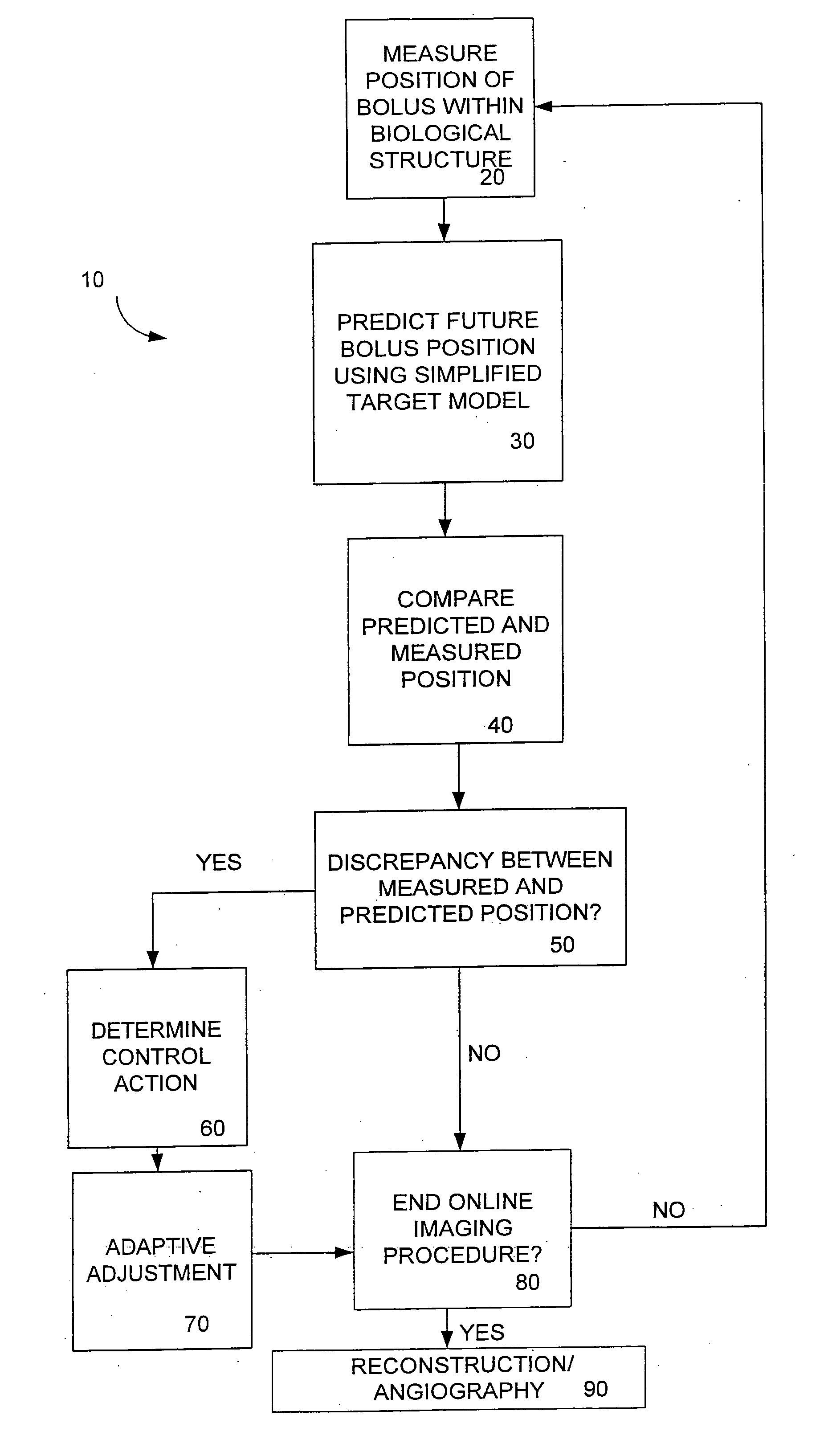
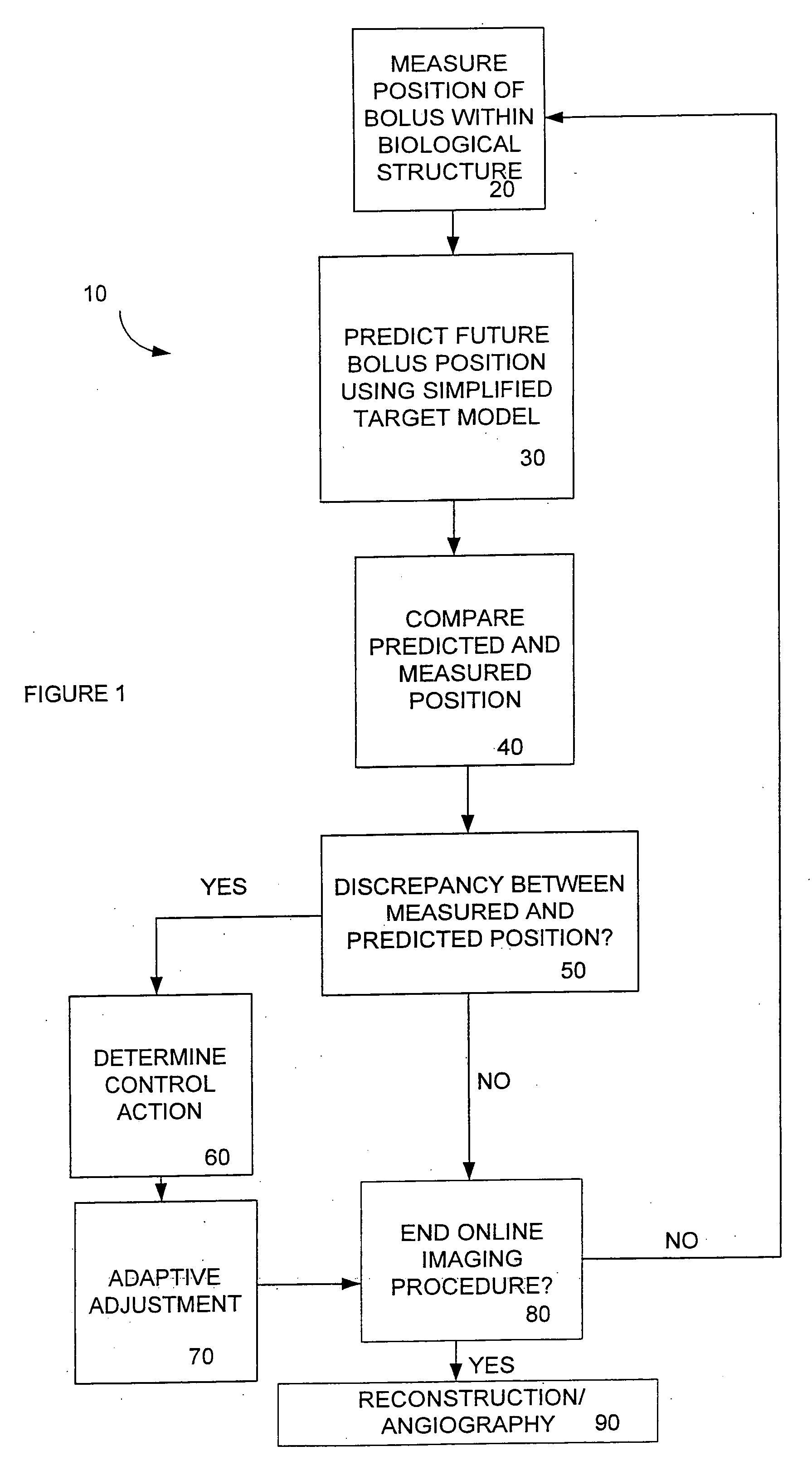
[0106] Injected contrast bolus was modeled by the above data, future bolus position and shape were predicted based on online-estimated patient parameters, and the patient table was controlled so that the trans-axial imaging aperture was synchronized with the predicted bolus peak position. The mathematical detail of the model used is provided...

example 2

[0112] A non-parametric model was implemented on a prototype CT scanner. This prototype consisted of a PC (personal computer), a Master Flex Pump 7550-30, a movable table controlled by a Vexta alpha stepping motor AS46 and a Pulnix-6700 camera. Plastic tubings configured similar to a patient's aorta and arteries were placed on the top of the table. The variable velocity pump was controlled by the PC and a patient's blood flow was stimulated by driving a bolus through plastic tubings. The velocity was assigned by a computer program. The camera, connected to the PC by a PCI card, provided the real time bolus position that simulated the CT imaging device. The imaging acquiring and processing were carried by NI IMAQ VISION DEVELOPMENT MODULES.

[0113] The model's algorithms were implemented by using the NI Labview software which is widely available. The stepping motor took commands from the PC through a serial port and controlled the table position, thereby simulating a patient table. Th...

example 3

[0114] The above discussed scheme with a non-parametric model was also tested on actual bolus propagation data that were collected from more than 20 patients. FIGS. 9 and 10 show results of two tests. In the figures, the actual bolus peak positions collected from patients are described by dash-dotted lines. The top diagrams are the CT table positions in solid lines using the current constant velocity technology. The bottom diagrams are the CT table positions in solid lines using the scheme discussed in this patent. Clearly, the adaptive bolus chasing CTA performs satisfactorily.

[0115] Unless otherwise expressly stated, it is in no way intended that any method set forth herein be construed as requiring that its steps be performed in a specific order. Accordingly, where a method claim does not actually recite an order to be followed by its steps or it is not otherwise specifically stated in the claims or descriptions that the steps are to be limited to a specific order, it is no way ...


PUM

PropertyMeasurementUnit
velocitiesaaaaaaaaaa
imaging reconstruction algorithmsaaaaaaaaaa
velocityaaaaaaaaaa

Abstract

A method of utilizing bolus propagation and control for contrast enhancement comprises measuring with an imaging device a position of a bolus moving along a path in a biological structure. The method further comprises predicting a future position of the bolus using a simplified target model and comparing the predicted future position of the bolus with the measured position of the bolus. A control action is determined to eliminate a discrepancy, if any, between the predicted position of the bolus and the measured position of the bolus and the relative position of the imaging device and the biological structure is adaptively adjusted according to the control action to chase the motion of the bolus.

Description

CROSS REFERENCE TO RELATED APPLICATIONS [0001] This application claims the benefit of U.S. Provisional Application No. 60 / 605,865, filed Aug. 31, 2004. The aforementioned application is herein incorporated in its entirety by reference.ACKNOWLEDGMENT [0002] This invention was made partially with government support under NIH / NIBIB grants EB001685 and EB002667-01 awarded by the National Institutes of Health. The government has certain rights in the invention.BACKGROUND OF THE INVENTION [0003] 1. Field of Invention [0004] The present invention generally relates to bolus-chasing angiography wherein imaging data is analyzed more effectively, tolerating greater modeling errors and uncertainties, using more powerful and robust control techniques and incorporating faster and more robust identification / estimation algorithms and techniques. [0005] 2. Description of Prior Art [0006] As known in the prior art, administration of a contrast material or bolus provides a short temporal window for op...

Claims


Application Information

Patent Timeline
Patent Type & Authority Applications(United States)
IPC IPC(8): G06F19/00G01N33/48G01N33/50G16Z99/00
CPCG06F19/3437G06T7/20G06T2207/30101A61B6/027G06T7/0016G16H50/50G16Z99/00
Inventor BAI, ER-WEIWANG, GEVANNIER, MICHAEL W.
Owner IOWA RES FOUND UNIV OF
Why Eureka
Try Eureka