Constant frequency self-oscillating amplifier

a constant frequency, self-oscillating technology, applied in amplifiers, amplifiers with semiconductor devices/discharge tubes, electrical devices, etc., can solve the problems of distorted output signal, low overall efficiency, and low distortion of digital signal processed by such prior art analog delta-sigma modulation. , to achieve the effect of improving overall efficiency and reducing distortion

Inactive Publication Date: 2006-08-17
NGUYEN TRANH TO
View PDF7 Cites 20 Cited by
  • Summary
  • Abstract
  • Description
  • Claims
  • Application Information

AI Technical Summary

Benefits of technology

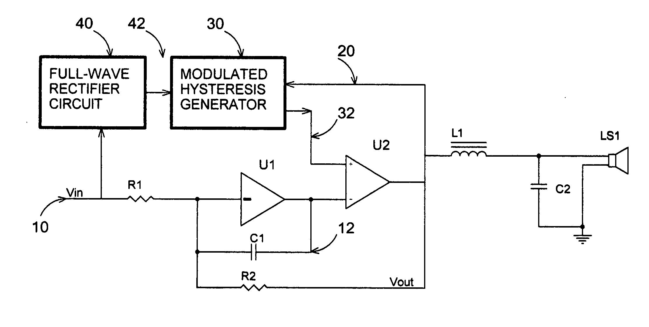
[0006] An object of the present invention is to provide a switch-mode amplifier using an analog Delta-Sigma modulator capable of operating at substantially constant switching frequency so that its distortion will be lower and its overall efficiency higher.

Problems solved by technology

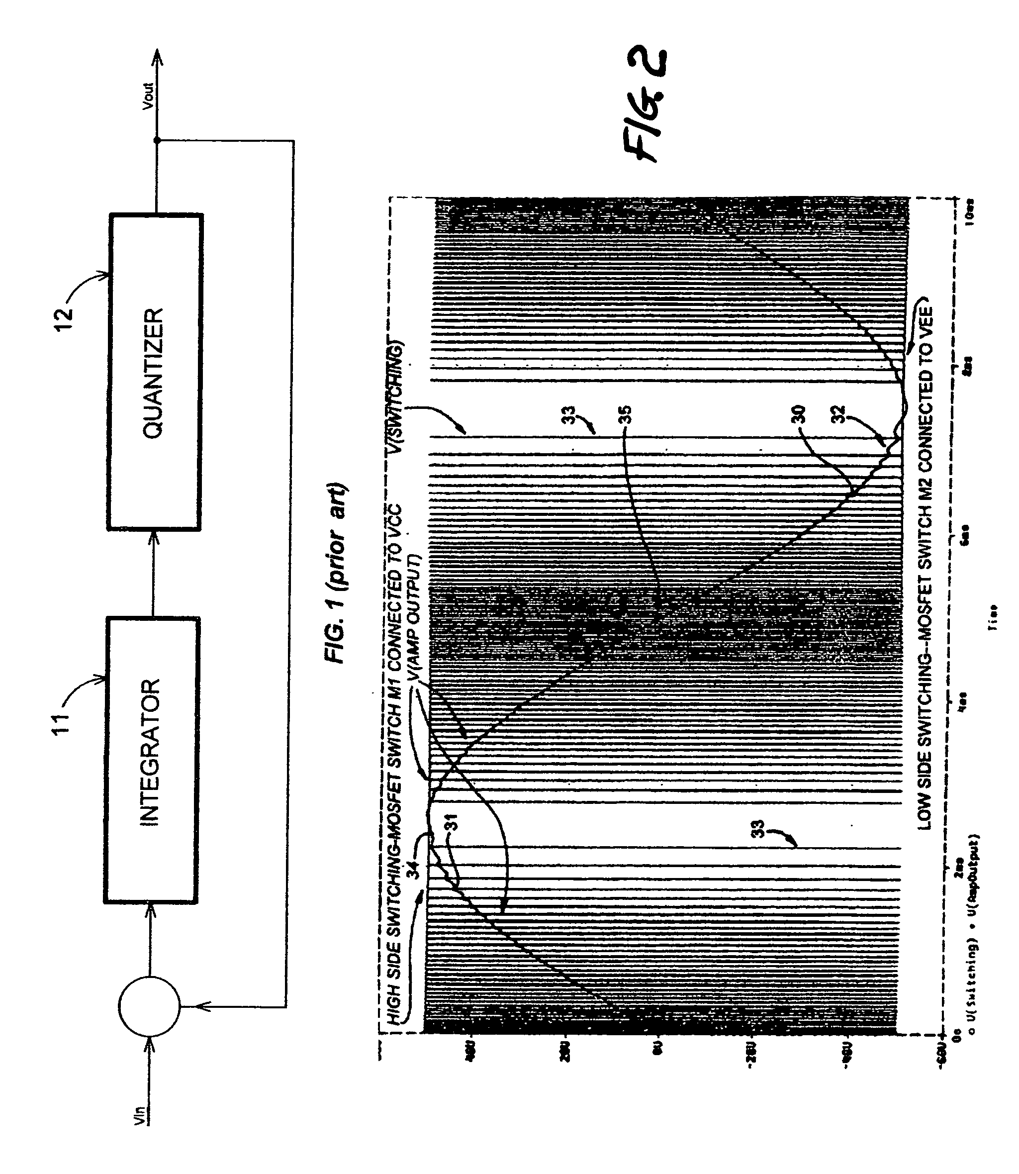
When the modulation index approaches unity, i.e. the input signal approaches the levels of the output voltage, the switching frequency of the analog Delta-Sigma modulator approaches zero, which results in a digital signal processed by such prior art analog Delta-Sigma modulation to be distorted.
Conversely, when the amplitude of the analog input signal is high, the density of the digital output signal is sparse, or low switching frequency.
Therefore, when the frequency of the input signal is high or its amplitude is high, the output signal will be distorted.

Method used


Image

  • Constant frequency self-oscillating amplifier
  • Constant frequency self-oscillating amplifier
  • Constant frequency self-oscillating amplifier

Examples


third embodiment

[0026] In a second and third embodiment, FIGS. 6A-6B, a signal proportional to the speaker voltage 50 or speaker current 60 or a combination thereof is fed into the integrator U1 to compensate for the resistances and any non-linearities of the components of the reconstruction filter L1-C2. Indeed, a choke used in the reconstruction filter may use a magnetic material for smaller size and lower cost, but magnetic materials are non-linear by their nature, and its winding has finite resistance that actually increases with frequency due to the skin and proximity effects. Likewise, a capacitor has its equivalent series resistance (ESR) and series equivalent inductance (ESL) and its capacitance may vary with applied voltage. While these non-linearities are small, they do degrade the total harmonic distortion (THD) of prior art switch-mode amplifiers. The feedback voltage or current or both voltage and current feedback from the speaker also reduces if not eliminates the peaking of the recon...

first embodiment

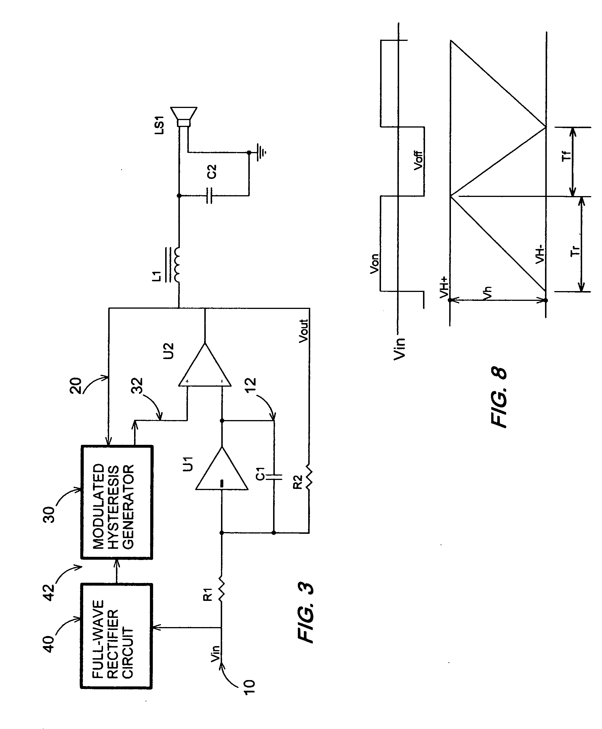
[0031] In another embodiment, FIG. 7, an additional gain block 70 is added to increase the open loop gain of the CFSOA, where the speaker voltage is fed back and compared to the input signal 10 to generate an error signal 71 that is now used as an input signal to an inner CFSOA of FIG. 3. Of course the transfer function of such an additional gain stage needs to be tailored to maintain the closed loop stability. Techniques for loop stability are well known to the skilled in the art, essentially the design must have loop phase shift less than 360 degrees when the loop gain is unity. Typically the transfer function of the gain block 70 ought to have at least one zero in its transfer function so that it doesn't add substantial phase shift around 0 dB crossing of the open loop gain of the amplifier. The additional loop gain provided by the gain block 70 will further reduce the distortion of the CFSOA and its output impedance by its gain.

[0032] From the description above, a number of adva...


PUM


Abstract

A self-oscillating switch-mode amplifier amplifying an input signal into a power output signal comprising an integrator for integrating the difference between the input signal and the output signal and a hysteretic comparator with thresholds which are modulated according to absolute value of the input signal. When the thresholds are quadratic function of the absolute value of the input signal, the switching frequency of the self-oscillating amplifier can be substantially constant.

Description

CROSS-REFERENCES TO RELATED APPLICATIONS [0001] This application claims the benefit of U.S. Provisional Application No. 60 / 654,059 filed Feb. 16, 2005.FIELD OF THE INVENTION [0002] The present invention relates to the technical field of signal modulation and amplification, and more particularly, to a self-oscillating amplifier using analog Delta-Sigma modulation. BACKGROUND [0003] Typically, analog Delta-Sigma modulation is used for converting an analog input signal to a switching or digital signal by comparing two threshold voltages with an error voltage formed by integrating the difference of the output voltage and the analog signal. When the error voltage exceeds an upper limit represented by the upper threshold voltage, the output changes state to 0. Vice versa, when the error voltage becomes lower than a lower limit represented by the lower threshold voltage, the output is changed to 1. The slope of the error voltage of such a modulator depends on the magnitude of the analog in...

Claims


Application Information

Patent Timeline
IPC IPC(8): H03F3/217
CPCH03F3/217H03F2200/331
Inventor NGUYEN, TRANH TO
Owner NGUYEN TRANH TO
Why Eureka
Try Eureka