Antireflection film, production method of the same, polarizing plate and display

a production method and anti-reflection technology, applied in the field of anti-reflection film, a production method of the same, a polarizing plate and a display, can solve the problems of deterioration of anti-reflection film hardness, scratch resistance, and film hardness not fully enough, so as to improve light resistance and flatness, improve scratch resistance, and improve the effect of scratch resistan

Inactive Publication Date: 2006-08-17
KONICA MINOLTA OPTO
View PDF2 Cites 79 Cited by
  • Summary
  • Abstract
  • Description
  • Claims
  • Application Information

AI Technical Summary

Benefits of technology

[0020] An object of the present invention is to provide an antireflection film exhibiting improved scratch resistance, pencil hardness, crack resistance, heiz, light resistance and flatness, and a production method thereof as well as to provide a polarizing plate and a display exhibiting an excellent visibility by using the antireflection film.

Problems solved by technology

However, any of these techniques tend to result in deterioration of hardness of the antireflective film (expressed, for example, by pencil hardness) or of the scratch resistance of the antireflection film.
However, the film hardness has not been fully enough and the film hardness of the film containing 20% by weight or more of hollow particles tends to become lower than the practical film hardness.
However, this method may give damage to the support since a temperature of 300° C. or more is necessary, and when the temperature is relatively low, for example, 100° C., rather long period is needed, which is not favorable for production.
As the methods to form a metal oxide layer, known are: (i) a method to form a silica film via a sol-gel process(refer to Patent Document 5); and (ii) a method to form a low refractive index layer via a sol-gel process (refer to Patent Document 5), both of which result in giving not fully sufficient scratch resistance.
The method to use a fluorine-containing resin as a binder has been known (for example, refer to Patent Documents 6-8) which also gives a low refractive index, however the film hardness of the resulting films are not fully enough.
However, some of these methods may result in deterioration of flatness of the optical film due to the heat deformation caused by the heat treatment, specifically in the production of a wide optical film.

Method used


Image

  • Antireflection film, production method of the same, polarizing plate and display
  • Antireflection film, production method of the same, polarizing plate and display
  • Antireflection film, production method of the same, polarizing plate and display

Examples


examples

[0400] The present invention will further be explained using the following examples, however, the present invention is not limited thereto.

[0401] The following material were loaded in turn and sealed in a container and the temperature was raised from 20° C. to 80° C. The loaded materials were stirred in the container at 80° C. for three hours, whereby the cellulose ester was completely dissolved. Silicon dioxide particles were added by preliminary dispersing the particles in a liquid containing a solvent to be used and a small amount of cellulose ester. Obtained liquid was filtered using Filter Paper No. 244 produced by Azumi Filter Paper Co., Ltd. to obtain Dope A.

(Preparation of Dope A)

[0402] Cellulose ester (cellulose triacetate; the acetylation degree of 2.9) 100 weight parts

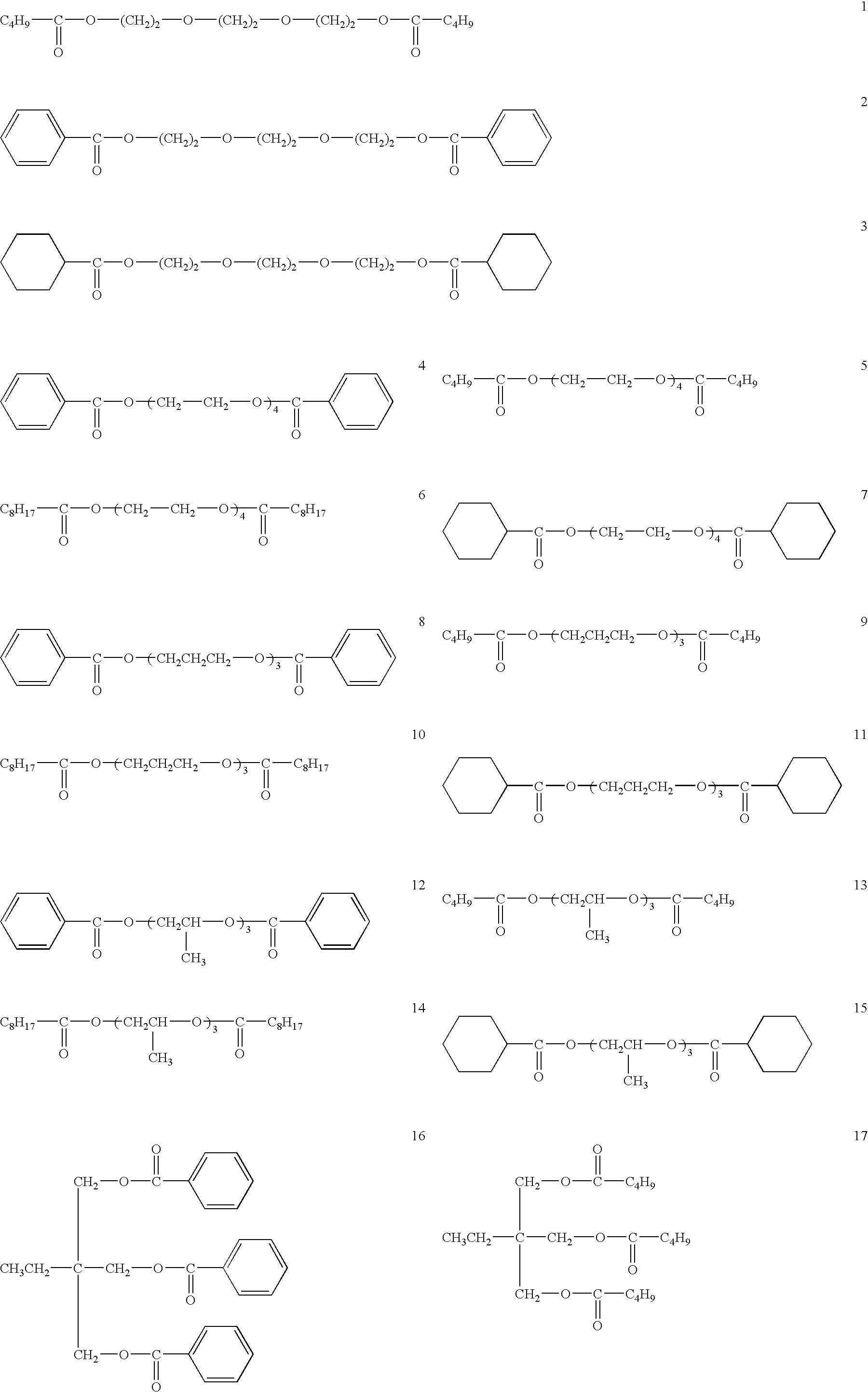
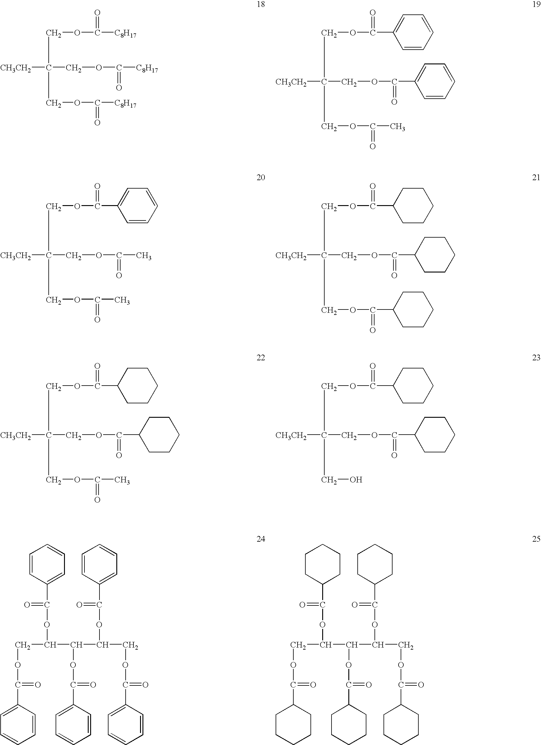
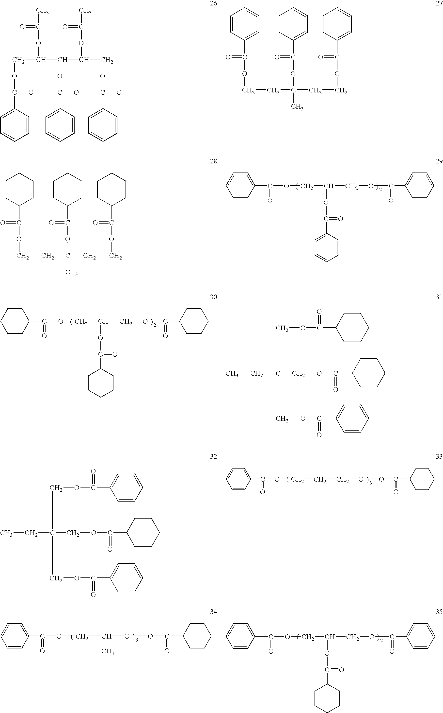
[0403] Trimethylolpropane tribenzoate 5 weight parts

[0404] Ethylphthalylethyl glycolate 5 weight parts

[0405] Silica particles (Aerosil R972V produced by Nippon Aerosil Co., Ltd.) 0.1 weight parts

[040...

example 2

[0484] Using hard coat films 3 and 16 produced in example 1, antireflection films were prepared as described below.

>

[0485] High refractive index layers 2-1 to 2-27 were produced in the same manner as high refractive index layer 1 except that the metal oxide particles, metal compound, ionizing radiation curable resin and surfactant used in high refractive index layer coating composition 1 were changed as shown in Table 3.

>

[0486] On each of the high refractive index layer 2-1 to 2-27, low refractive index layer coating composition 1 used in example 1 was applied by an extrusion coater and dried at 100° C. for 1 minute, followed by being irradiated with 0.1 J / cm2 of UV rays to harden the layer. The layer was further heat cured at 120° C. for 5 minute. The layer thickness was 95 nm. Thus, antireflection films 26-56 as shown in Table 4 were obtained.

>

[0487] Each of antireflection films 26-53 (length: 1000 m) was wound to a plastic core and was subjected to a heat treatment for 4 days ...

example 3

[0494] Using antireflection films 1-56 produced in examples 1 and 2, polarizing plates were produced as described below, each of which was installed in a display panel to evaluate the visibility.

[0495] Polarizing plates 1-56 were produced by using each antireflection film described above and a cellulose ester optical compensation film, KC8UCR-5 (produced by KONICA MINOLTA, OPTO, INC.).

(a) Production of Polarizing Film

[0496] 100 weight parts of polyvinyl alcohol having a saponification degree of 99.95% and polymerization degree of 2400 (hereafter referred to as PVA) was mixed with 10 weight parts of glycerin and 170 weight parts of pure water. The mixture was melted, kneaded, defoamed and melt-extruded from a T-die on a metal roll to form a film. The film was dried and heat treated to obtain a PVA film having an average thickness of 40 μm, water content of 4.4% and a film width of 3 m.

[0497] The PVA film was continuously subjected to preliminary swelling, dyeing, uniaxial wet str...


PUM


Abstract

An antireflection film comprising a transparent substrate film having thereon a hard coat, a high refractive index layer and a low refractive index layer, wherein: (i) the high refractive index layer is formed by applying a coating solution containing the following (a) to (c); (ii) the low refractive index layer is formed by applying a coating solution containing the following (d) and (e); (iii) the antireflection film is heat treated, wherein (a) metal oxide particles having an average primary particle diameter of 10 to 200 nm; (b) a metal compound; (c) an ionizing radiation curable resin; (d) an organosilicon compound having a prescribed structure, a hydrolyzed compound of the organosilicon compound, a decomposed compound of the organosilicon compound or a polycondensed compound of the organosilicon compound; and (e) hollow silica particles each having an outer shell, and a void or a porous portion in the inside.

Description

[0001] This application is based on Japanese Patent Application No. 2005-038960 filed on Feb. 16, 2005 Japanese Patent Office, the entire content of which is hereby incorporated by reference. FIELD OF THE INVENTION [0002] The present invention relates to an antireflection film, a production method of the same, a polarizing plate and a display. BACKGROUND OF THE INVENTION [0003] With respect to an antireflection film used on the outermost surface of a display, for example, a liquid crystal display, proposed has been a technique to form a low reflectivity surface by providing an antireflection film using optical interference. [0004] In order to lower the reflectivity, a technique to lower the refractive index of the low refractive index layer on the outer most surface of a display has been proposed, in which proposed has been a method to use a low refractive index material or to increase the number and / or volume of voids in the layer to lower the refractive index. However, any of thes...

Claims


Application Information

Patent Timeline
Patent Type & Authority Applications(United States)
IPC IPC(8): G02B1/10
CPCG02B1/111A61C17/14A61C17/028A47K1/04A47K5/04A47K1/08
Inventor OJIMA, YOSHIKAZUMAEJIMA, KATSUMIIKEDA, TOSHIYUKI
Owner KONICA MINOLTA OPTO
Why Eureka
Try Eureka