Artificial cardiac pump

a technology of artificial heart pump and rotor, which is applied in the direction of prosthesis, liquid fuel engine, therapy, etc., can solve the problems of mechanical loss and damae, both sides are worn down and burned, and the rotor cannot be rotated smoothly

Active Publication Date: 2006-08-17
NIPRO CORP
View PDF8 Cites 20 Cited by
  • Summary
  • Abstract
  • Description
  • Claims
  • Application Information

AI Technical Summary

Problems solved by technology

Thus, the both sides are worn down and burned.
Such mechanical loss and damaes are occurred.
The rotor cannot be rotated smoothly and such a situation is baneful for the non-contact relation and the rotor would be makes vibrated.
Mechanical loss and damage caused by rotating the rotor in blood cannot be ignored.
T...

Method used


Image

  • Artificial cardiac pump
  • Artificial cardiac pump
  • Artificial cardiac pump

Examples


first embodiment

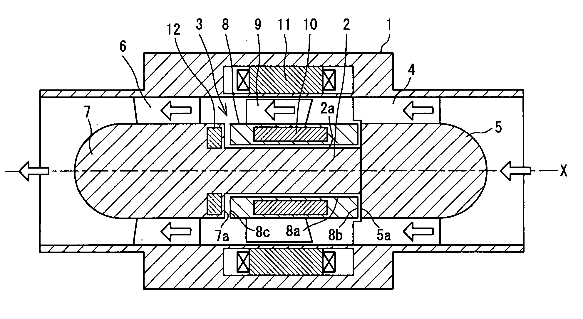
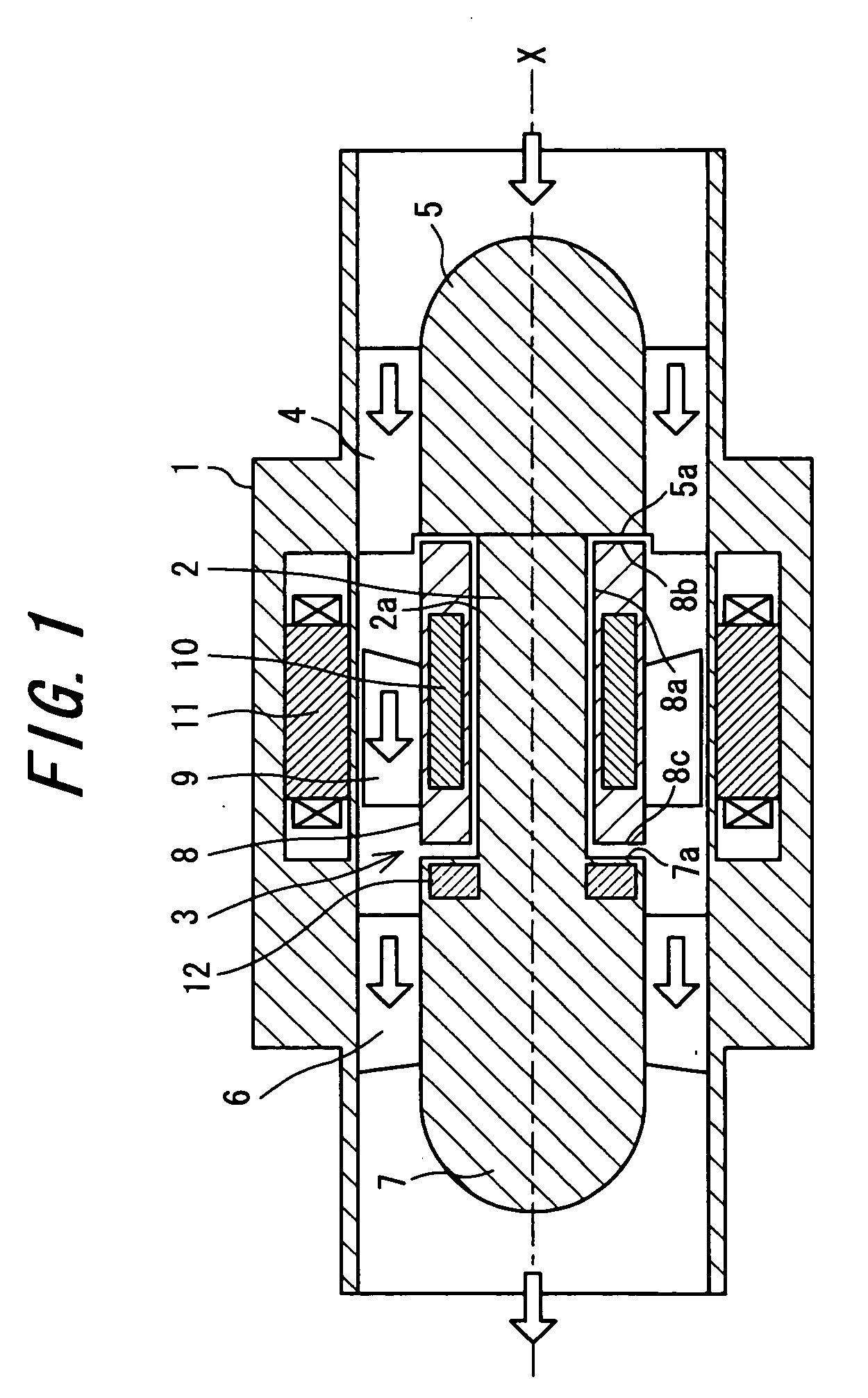
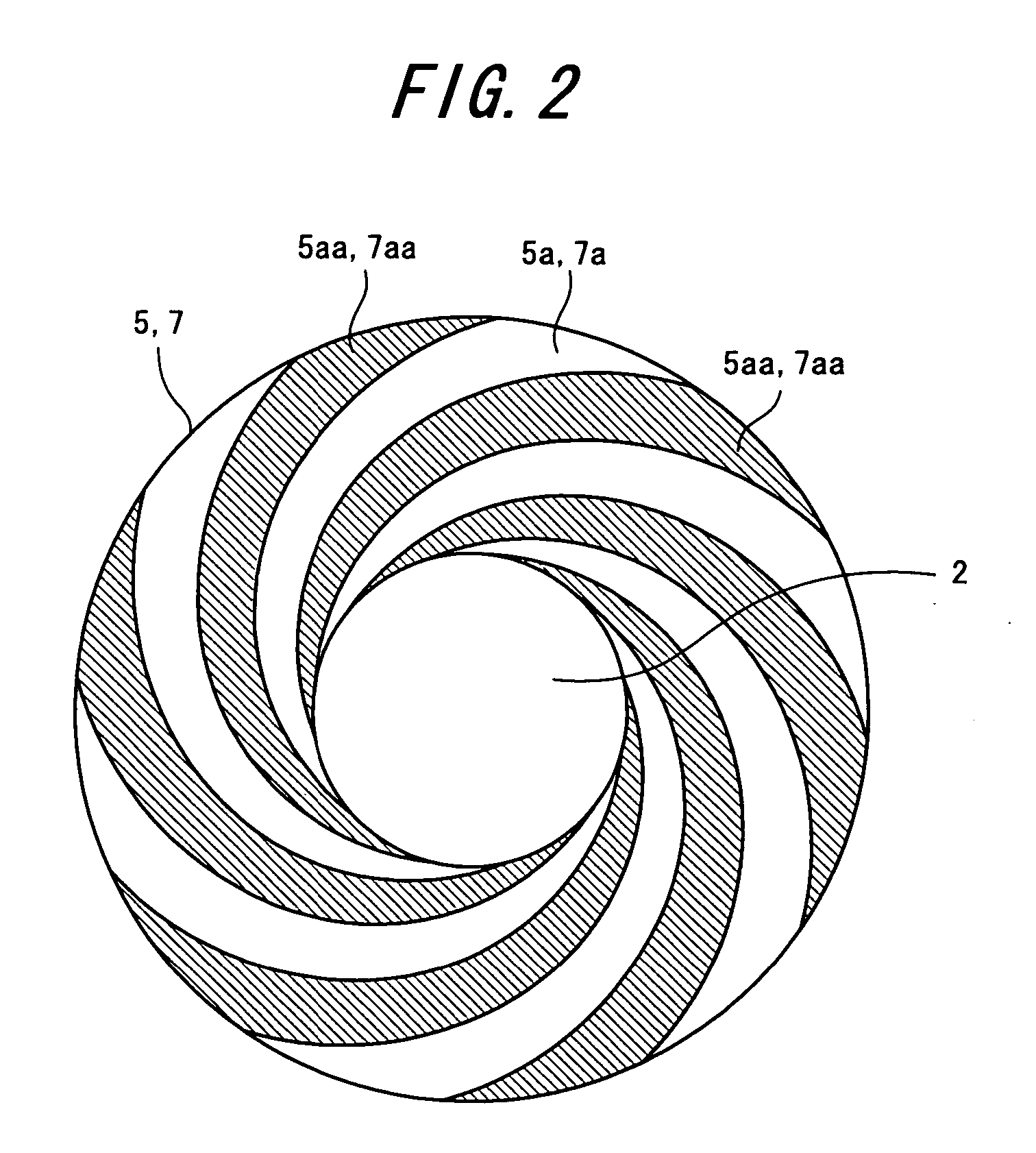
[0035] An embodiment of an artificial cardiac pump according to the present invention will be described with reference to the accompanying drawings. FIG. 1 shows a vertical cross sectional view of an embodiment of an artificial cardiac pump according to the present invention. FIG. 2 shows a plan view of a rear end surface of a front side fixed body and a front end surface of a rear side fixed body for showing thrust hydrodynamic grooves in its artificial cardiac pump. In the drawings, the same named components indicates the same numerals, respectively. Therefore, the description thereof is omitted.

[0036] As shown in FIG. 1, the embodiment of the artificial cardiac pump according to the present invention mainly comprises a cylindrical housing 1, a fixed axial body 2 as a central axis X in the housing, a rotor 3 that is an impeller rotatively supported in the housing with respect to the axial body 2 and a driving mechanism for rotating the rotor 3. By rotating the rotor 3, blood is t...

second embodiment

[0050] In the next, the second embodiment of the artificial cardiac pump according to the present invention will be described with reference to the drawings. FIG. 4 shows a cross sectional view for showing a structure of the second embodiment of the artificial cardiac pump according to the present invention. The embodiment is one of variations modified from the first embodiment as described above, wherein the same named components is numbered with the same reference numbers in the first embodiment of the artificial cardiac pump, respectively. The explanation thereof is omitted.

[0051] As shown in the drawings, the second embodiment of the artificial cardiac pump comprises a permanent magnet 13 as the first magnet and a permanent magnet 14 as the second magnet instead of the magnetic body 12. The permanent magnet 13 is installed in the sleeve at which the permanent magnet 13 is confronting with a rear end surface 5a of a front side fixed body 5. The permanent magnet 14 is installed i...


PUM


Abstract

An artificial cardiac pump, comprising an impeller (3) rotatably supported on a fixed shaft body (2) in a housing (1) and a drive mechanism rotating the impeller, wherein blood is taken in from the front side and force-fed to the rear side by the rotation of the impeller (3). The shaft body (2) is connected between a front side fixed body (5) fixed to a straightening plate (4) joined to the housing (1) at the front of the impeller (3) and a rear side fixed body (7) fixed to a diffuser (6) joined to the housing (1) at the rear of the impeller (3). The impeller (3) further comprises a sleeve (8) having an inner peripheral surface opposed to the outer peripheral surface of the shaft body (2) through a minute clearance and front and rear end faces opposed to the rear end face of the front side fixed body (5) and the front end face of the rear side fixed body (7) through minute clearances, and an impeller (9) joined to the outer peripheral surface of the sleeve (8). The drive mechanism further comprises a polar anisotropical permanent magnet (10) enclosed in the sleeve (8) and a rotating field generator (11) enclosed in the housing (1).

Description

FIELD OF THE INVENTION [0001] The present invention relates to an artificial cardiac pump for force-feeding blood as a substitute or an auxiliary of a heart of a living body. BACKGROUND OF THE INVENTION [0002] In a conventional art, an artificial cardiac pump comprises a rotatable impeller so as to be taken and force-fed blood. In general, artificial cardiac pumps can be divided into a group of axial-flow propeller pumps and a group of rotary / centrifugal pumps. Upon comparing with the group of the axial-low propeller pumps and the group of rotary / centrifugal pumps, the group of the axial-flow propeller pumps has an advantage in view of down-sizing. Hereinafter, it will be described an artificial cardiac pump with an axial-flow propeller pump. [0003] For example, a conventional artificial cardiac pump comprises a rotor such as an impeller, wherein both ends of the rotor are rotatably supported in a housing and a polar anisotropic permanent magnet is installed in the rotor, and a moto...

Claims


Application Information

Patent Timeline
IPC IPC(8): A61N1/362F04D29/046A61M1/10F04D7/00F04D13/02
CPCA61M1/101A61M1/1015A61M1/1017A61M1/1031A61M1/122A61M60/824A61M60/422A61M60/148A61M60/216A61M60/10A61M60/818
Inventor OKUBO, TAKESHIOSAKA, TOSHIYUKIYAMAMOTO, YASUHARUSANO, TAKESHIMIYAMOTO, YUSUKEMIYAGAWA, KAZUYOSHI
Owner NIPRO CORP
Why Eureka
Try Eureka