Biomedical electrodes and biomedical electrodes for electrostimulation

a biomedical electrode and electrode technology, applied in the field of biomedical electrodes, can solve the problems of ineffective use of silver ink, inconvenient use of ink, and high cost of ink, and achieve the effects of high conformability, high conductive porous material, and high conductive conductivity

Inactive Publication Date: 2006-08-17
HEALY JAMES W
View PDF5 Cites 24 Cited by
  • Summary
  • Abstract
  • Description
  • Claims
  • Application Information

AI Technical Summary

Benefits of technology

[0012] According to one aspect, there is provided a biomedical electrode that incorporates electrolytically plated or metallized woven ripstock, non-woven fabric, yarn and/or knitted mesh. The fabric can be thin, flexible, uniform, and highly conformable. More specifically, loosely woven or non-woven fabric can be electrolytically metallized such that it is conductive on both sides (e.g., top a

Problems solved by technology

According to McAdams, the conductive silver coating has an irregular surface with a 4 μm peak to trough height, which could cause hot spots due to non-uniform current distribution.
While the above cited art presents improvements for biomedical electrodes, they each suffer from a number of technical problems.
For example, the use of silver ink as disclosed in McAdams is quite inefficient.
Further, the binder and solvents in the ink can outgas and interact with the conductive gel, and the ink is quite expensive.
With respect to the technique disclosed in Axelgaard, costs can be relatively high and the resulting fabric may suffer from relatively low conductivity and uniformity.
Further, production problems can

Method used


Image

  • Biomedical electrodes and biomedical electrodes for electrostimulation
  • Biomedical electrodes and biomedical electrodes for electrostimulation
  • Biomedical electrodes and biomedical electrodes for electrostimulation

Examples


Embodiment Construction

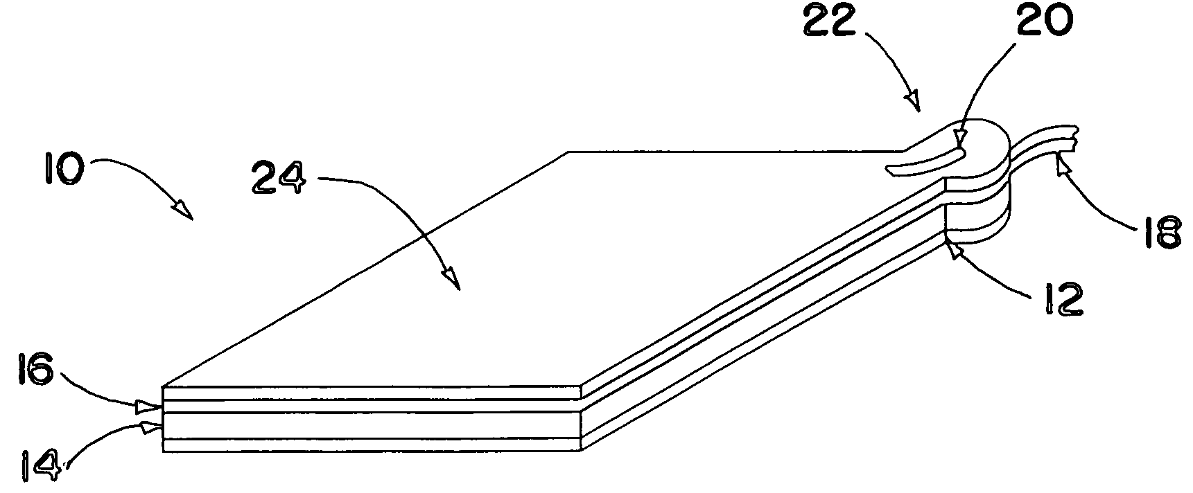
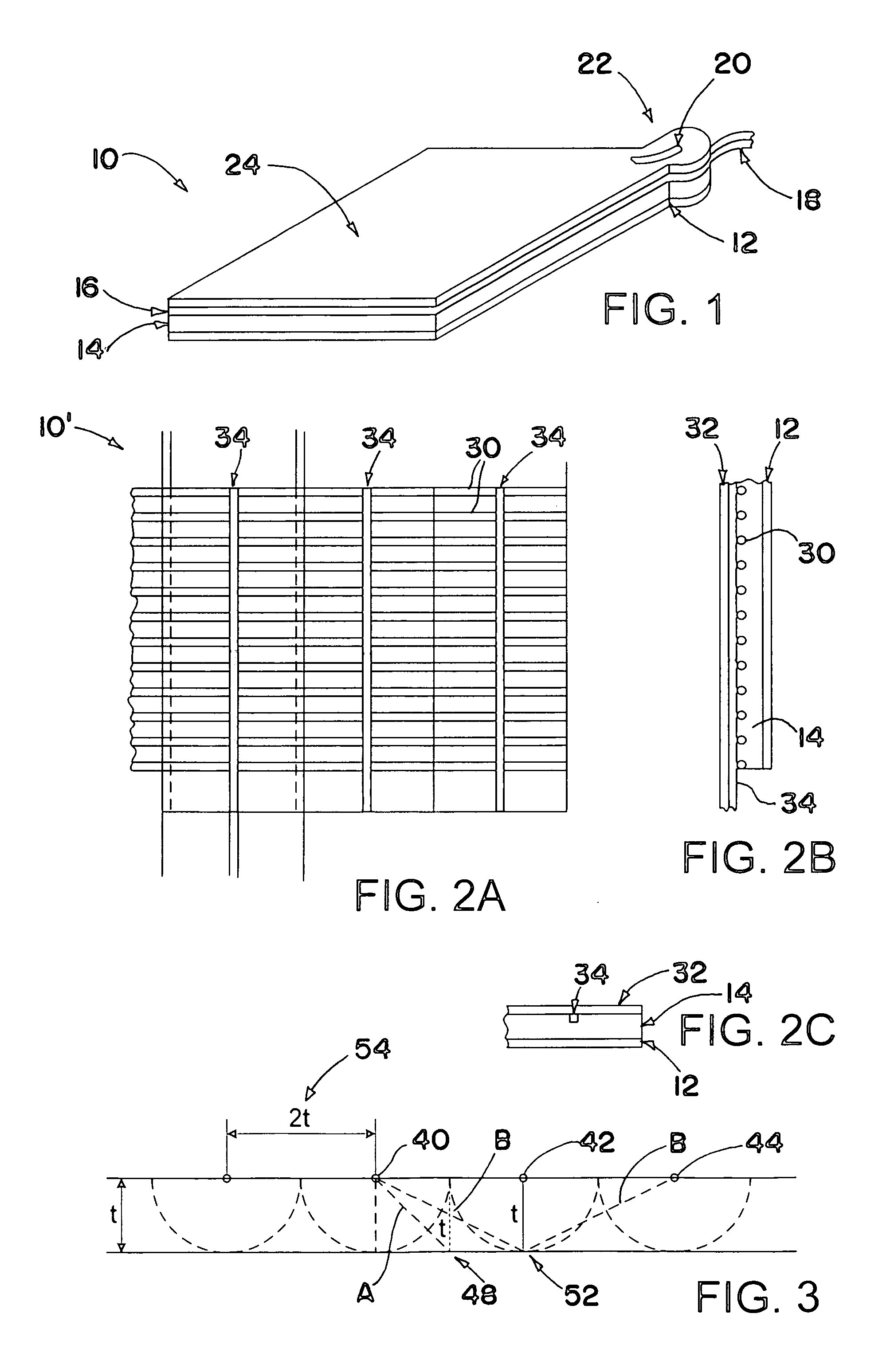
[0029]FIG. 1 illustrates an electrode 10 in accordance with an embodiment of the invention. The electrode 10 includes a first layer 12, which can be a polymer film (e.g., 5 mil PET) that operates as a release liner. The electrode 10 includes a second layer 14 in contact with the first layer 12. The second layer 14 can be a conductive gel layer, which can be purchased, for example, from Amgel Technologies, a division of Axelgaard Manufacturing, or from Procam Medical, part of Tyco International's subsidiary, Ludlow Corporation. The volume resistivity of the gel can be about 1500 ohm-cm, for example, and is available in a thickness of 35 mils.

[0030] The sheet resistivity of the gel (the second layer 14) can be determined by Equation 1, wherein W is the sheet width in centimeters, L is the sheet length in centimeters, ρ1 is the volume resistivity in ohm-cm, t is the thickness in centimeters, and ρ is the sheet resistivity in ohms / □. ρ=ρ1*Lt*WEquation⁢ ⁢1

[0031] For example, a sheet ha...


PUM


Abstract

A biomedical electrode for transmitting and/or receiving electrical signals to/from a patient is disclosed. The electrode includes a metallized fabric, wherein metallization of the fabric is connected at least on a top side and a bottom side of the fabric so as to uniformly transmit or receive the electrical signals. A conductive gel adhesive in contact with the metallized fabric. The electrode can be fabricated using a continuous web process, thereby reducing the cost of manufacturing the electrode.

Description

RELATED APPLICATION DATA [0001] This application is a continuation-in-part of U.S. Non-Provisional application Ser. No. 11 / 205,750 filed on Aug. 17, 2005, which claims priority to U.S. Provisional Application Nos. 60 / 602,188, filed on Aug. 17, 2004, and 60 / 643,676, filed on Jan. 13, 2005, each of which are incorporated herein by reference in their entirety. [0002] This application claims priority of U.S. Provisional Application No. 60 / 643,676, filed on Jan. 13, 2005.BACKGROUND OF THE INVENTION [0003] There are many designs for biomedical electrodes. Typically, these electrodes include a conductive adhesive hydrogel, which is in contact with a patient's skin, a conductive material in contact with the hydrogel so as to apply a uniform voltage or current to the gel, and a wire from the conductive material to a voltage source. Additionally, the electrodes may be covered by a protective dielectric film, such as, for example, Vinyl, Polyethylene, Polystyrene and Polyester. [0004] U.S. Pat...

Claims


Application Information

Patent Timeline
IPC IPC(8): A61B5/04A61N1/04
CPCA61B5/04087A61N1/0492A61B2562/0215A61B5/24A61B5/259
Inventor HEALY, JAMES W.
Owner HEALY JAMES W
Why Eureka
Try Eureka